
Related Manuals for Mitsubishi Heavy Industries WRK20MGC1


Summary of Contents for Mitsubishi Heavy Industries WRK20MGC1
- Page 1 MGC1 MGC1 MGC1 MGC1 ITSUBISHI HEAVY INDUSTRIES IN IN AIR CONDITIONERS CO TD A C...
- Page 4 ......................03 ..................09 ....................10 ....................11 ......................12 ....................13 ....................15 ......................16...
- Page 5 • • • • • • • • • • • • • • •...
- Page 6 1. 安裝必須由授權經銷商或受過專業訓練人員進行。有缺陷的安裝會導致漏水、觸電或火災。...
- Page 11 18°C-43°C (64°F-109°F) 18°C ~ 52°C 64°F ~ 126°F 17°C-32°C (62°F-90°F) -5°C-24°C (23°F-76°F) 0°C-27°C (32°F-80°F)
- Page 12 WRK20MGC1 WRK20MGC1 注意: 空調在進入配置模式(AP)後,用戶屆時將無法操控空調直至配置結束或8分鐘過後。如需即時取消配置模式(AP),用戶 可通過斷開電源或拔下電置,重啟空調。...
- Page 15 或當有過多冷凝水時,會造成溢水 的現象,如果您對噪音敏感或擔心有溢水的風險,...
- Page 20 Warning Read Warning Before Operation and Installation Incorrect installation due to ignore of instructions can cause serious damage or injury. WARNING Installation (Space) - Where refrigerant pipes shall be compliance with national gas regulations. - That mechanical connections shall be accessible for maintenance purposes. - In cases that require mechanical ventilation, ventilation openings shall be kept clear of obstruction.
- Page 21 Transportation, marking and storage for units 1. Transport of equipment containing flammable refrigerants Compliance with the transport regulations 2. Marking of equipment using signs Compliance with local regulations 3. Disposal of equipment using flammable refrigerants Compliance with national regulations 4. Storage of equipment/appliances The storage of equipment should be in accordance with the manufacturer’s instructions.
-
Page 22: Table Of Contents
Table of Contents Safety Precautions ................Unit Parts Identification ................. Operation Instructions ................ Care and Maintenance ................ Water Drainage ..................Installation Instructions ..............Troubleshooting ................... Specifications ..................Environment Effective from 31 December 2018, the disposal licensing control, import and export permit control and landfill disposal ban in respect of abandoned regulated electrical equipment (REE) have r t , r , t... -
Page 23: Safety Precautions
Safety Precautions Read Safety Precautions Before Operation and Installation Incorrect installation due to ignoring instructions can cause serious damage or injury. The seriousness of potential damage or injuries is classified as either a WARNING or CAUTION. CAUTION WARNING This symbol indicates the possibility of This symbol indicates the possibility property damage or serious consequences. - Page 24 ELECTRICAL WARNINGS Only use the specified power cord. If the power cord is damaged, it must be replaced by the manufacturer, its service • agent or similarly qualified persons in order to avoid a hazard. Keep power plug clean. Remove any dust or grime that accumulates on or around the plug. Dirty plugs can cause fire •...
- Page 25 UV-C lamp(Applicable to the unit contains an UV-C lamp only) This appliance contains a UV-C lamp. Read the maintenance instructions before opening the appliance. 1. Do not operate UV-C lamps outside of the appliance. 2. Appliances that are obviously damaged must not be operated. 3.
- Page 26 Explanation of symbols displayed on the unit(For the unit adopts R32 Refrigerant only): This symbol shows that this appliance This symbol shows that a service used a mildly flammable refrigerant. personnel should be handling If the refrigerant is leaked and exposed this equipment with reference WARNING CAUTION...
- Page 27 Marking to the equipment continues to be visible and legible. Markings and signs that are illegible shall be corrected; Refrigeration pipe or components are installed in a position where they are unlikely to be exposed to any substance which may corrode refrigerant containing components, unless the components are constructed of materials which are inherently resistant to being corroded or are suitably protected against being so corroded.
- Page 28 render the unit safe. This process may need to be repeated several times. Compressed air or oxygen shall not be used for this task. Flushing shall be achieved by breaking the vacuum in the system with OFN and continuing to fill until the working press- ure is achieved, then venting to atmosphere, and finally pulling down to a vacuum.
-
Page 29: Unit Parts Identification
When flammable refrigerant are employed, appliance shall be stored in a well -ventilated area. Operating temperature When your air conditioner is used outside of the following temperature ranges, certain safety protection features may activate and cause the unit to disable. 18°C-43°C (64°F-109°F) Outdoor Temperature 18°C-52°C (64°F-126°F) (For special tropical models) -
Page 30: Operation Instructions
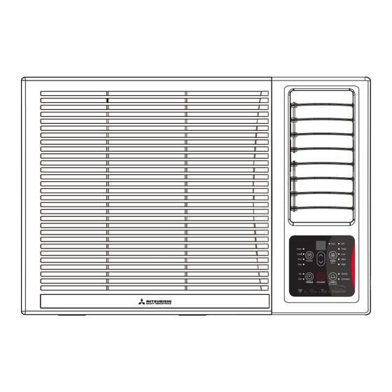
The vent control is located above the control knobs. The operation method and the shape may vary in different models (see the following figures) For maximum cooling efficiency, CLOSE the vent. It will allow internal air circulation. OPEN the vent to discharge stale air. WRK20MGC1 CLOSE VENT... - Page 31 NOTE: Some models without MED fan speed feature and (or) AUTO mode feature and (or) swing feature. POWER: Press the POWER keypad to turn the unit on/off. MODE: Press the "MODE" keypad to select the appropriate operating mode. The mode selection will alternate between AUTO, COOL, FAN and DRY.The indicator light beside the "MODE"...
- Page 32 Turbo function(on some models) Press the TURBO button by remote controller on COOL mode, the air condetioner goes into powerful cooling operation. Press again to cancel the TURBO function. ECO function(on some models) Press the ECO button by remote controller on COOL mode to enter the energy efficient mode. LED Display: •...
-
Page 33: Care And Maintenance
CARE AND MAINTENANCE BEFORE CLEANING OR MAINTENANCE ALWAYS TURN OFF YOUR AIR CONDITIONER SYSTEM AND DISCONNECT ITS POWER SUPPLY BEFORE CLEANING OR MAINTENANCE. Cleaning Your Unit IMPORTANT The cabinet and front panel may be dusted with an oil-free cloth or washed with a cloth dampened in a solution of warm water and mild liquid dishwashing detergent. - Page 34 Rubber plug Rubber plug Drain pan Drain outlet Screw Bottom drainage Bottom drain hole Rubber plug Back drain hole Back drain hole Drain joint Seal Back drainage Non-drainage Note on the product The rated cooling performance is tested under non-drainage status. Make sure that water will not leak from the surrounding area when rubber plug and joint were used.
-
Page 35: Installation Instructions
INSTALLATION INSTRUCTIONS Prior to installation CAUTION: Before installing, remove all packaging from inside the carton, along with any inserts placed into the side louvers(if any). Step 1: Select the best location Remove inserts placed 1. To avoid vibration and noise, make sure the unit is installed securely and firmly. into the side louvers 2. - Page 36 Model C: 1. Remove four screws located on both sides and the back of the cabinet as shown in Fig.5C. 2. Grasp the handle on the chassis and carefully slide the air cond- itioner out of the cabinet.(see Fig.6) Model D: 1.
- Page 37 Step 8: Install the air filter and front panel 1. Insert the air filter into the frame’s slot from upside to underside. (See Fig. 2) 2. Hang the front panel on the frame’s buckle, then press the front panel into the frame’s slot until you hear a click (see Fig.11). 3.
-
Page 38: Troubleshooting
Troubleshooting SAFETY PRECAUTIONS If ANY of the following conditions occurs, turn off your unit immediately! The power cord is damaged or abnormally warm You smell a burning odor The unit emits loud or abnormal sounds A power fuse blows or the circuit breaker frequently trips Water or other objects fall into or out of the unit DO NOT ATTEMPT TO FIX THESE YOURSELF! CONTACT AN AUTHORIZED SERVICE PROVIDER IMMEDIATELY! -
Page 39: Specifications
SPECIFICATIONS Unit dimensions: MODEL(Btu/h) BODY DIMENSION(HxWxD)(mm) 320x415x445 5000~6000 346x535x450 346x535x450 Note: For the different customization requirements, the deepth of the panel 7000~9000 346x585x450 may be slightly different. So the dimension of “D” is for reference only. 350x450.6x675 350x450.6x675 350x675x450 9000~12000 400x640x560 380x560x600 428x660x780... - Page 40 The design and specifications are subject to change without prior notice for product improvement. Consult with the sales agency or manufacturer for details. Any updates to the manual will be uploaded to the service website, please check for the latest version.
Need help?
Do you have a question about the WRK20MGC1 and is the answer not in the manual?
Questions and answers