Advertisement
Quick Links
SUPER HIGH EFFICIENCY CONDENSING
TANKLESS WATER HEATER
USE AND CARE MANUAL
With Installation Instructions
for the Installer
Condensing Direct Vent
199,900 Btu/hr, 180,000 Btu/hr,
157,000 Btu/hr and 120,000 Btu/hr Models
WARNING:
If the information in these instructions is not
followed exactly, a fire or explosion may result,
causing death, personal injury, or property dam-
age.
For Your Safety!
• Do not store or use gasoline or other flammable
vapors and liquids in the vicinity of this or
any other appliance. To do so may result in an
explosion or fire.
• Installation and service must be performed by
a qualified installer, service agency, or the gas
supplier.
Print 2D
Bar Code
Here
CERTIFIED
®
R
What to Do If You Smell Gas
• Do not try to light any appliance.
• Do not touch any electrical switch; do not use
any phone in your building.
• Immediately call your gas supplier from a
neighbor's phone. Follow the gas supplier's
instructions.
• If you cannot reach your gas supplier, call the
fire department.
• Do not return to your home until authorized by
the gas supplier or fire department.
Do not destroy this manual. Please read carefully
and keep in a safe place for future reference.
ULTRA
Low NOx
Emissions
ww w. ah r i d i rec t or y. org
SCAQMD Rule 1146.2
AP21820 Rev 04
Advertisement

Related Manuals for Rheem scooter


Summary of Contents for Rheem scooter
- Page 1 SUPER HIGH EFFICIENCY CONDENSING TANKLESS WATER HEATER USE AND CARE MANUAL With Installation Instructions for the Installer Condensing Direct Vent 199,900 Btu/hr, 180,000 Btu/hr, 157,000 Btu/hr and 120,000 Btu/hr Models ULTRA Low NOx Emissions ww w. ah r i d i rec t or y. org SCAQMD Rule 1146.2 CERTIFIED ®...
- Page 2 CONTENTS Important Safety Information Using Your Water Heater Activating the Water Heater �������������������������������������������������51, 52 Safety Precautions ��������������������������������������������������������������� 2 – 8 Setting the Water Temperature �������������������������������������������53 – 56 Product Information WiFi Setup ����������������������������������������������������������������������������������������������������56 Product Information �������������������������������������������������������������������� 8 Recirculation Pump Control �����������������������������������������������57 – 61 Specifications �����������������������������������������������������������������������...
- Page 3 IMPORTANT SAFETY INFORMATION Water Heater Venting Safety DANGER: D A N G E R • Failure to install and properly vent the water heater to the outdoors as outlined in the “Venting” section of the Installation Instructions in this manual will result in death from fire, explosion, or asphyxiation from carbon monoxide.
- Page 4 IMPORTANT SAFETY INFORMATION Water Supply Safety DANGERS: CAUTIONS: D A N G E R • WATER TEMPERATURE SETTINGS • This water heater must only be used – Safety and energy conservation with the following water supply system are factors to be considered when conditions: selecting the water temperature –...
- Page 5 IMPORTANT SAFETY INFORMATION Natural Gas and Liquefied Petroleum Safety DANGERS: WARNINGS: • Never attempt to convert the water heater from natural • The installation of gas piping must comply with local gas to LP or vice versa. The water heater must only utility company requirements and/or in the absence of use the fuel type in accordance with the listing on the local codes, use the latest edition of National Fuel Gas...
- Page 6 IMPORTANT SAFETY INFORMATION Before operating this water heater, be sure to read and follow the instructions on the label pictured below and all other labels on the water heater, as well as the warnings printed in this manual. Failure to do so can result in unsafe operation of the water heater, resulting in death, personal injury, or property damage.
- Page 7 IMPORTANT SAFETY INFORMATION Electrical Safety CAUTIONS: DANGER: • Label all wires prior to disconnecting for service. Wiring • Shock Hazard – Make sure the electrical power to the errors can cause dangerous and improper operation. water heater is off to avoid electric shock that will Verify correct operation after servicing.
- Page 8 IMPORTANT SAFETY INFORMATION General Installation and Maintenance Safety WARNINGS: SAFETY PRECAUTIONS: • This water heater must be installed in accordance Read this manual entirely before installing and/or with these instructions, local codes, utility company operating the water heater. requirements and/or in the absence of local codes, Use this water heater only for its intended purpose as use the latest edition of the American National described in this Use and Care Manual.
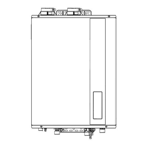
- Page 9 PRODUCT INFORMATION Specifications – Direct-Vent Models Front View Top View 3.358 in 5.500 in (85 mm) (140 mm) 6.331 in (161 mm) 25.157 in 23.661 in (639 mm) (601 mm) 5.740 in (146 mm) 1.555 in (39 mm) 17.717 in (450 mm) Bottom View 5.374 in...
- Page 10 PRODUCT INFORMATION Specifications English Rating Label The following product information can be found from the rating label on this water heater. A. Model Number B. Serial Number C. Data Bar Code D. Heater Type E. Installation Type F. Type of Gas G.
- Page 11 PRODUCT INFORMATION The graphic below illustrates the pressure drop across the water heater. Please ensure ample water supply pressure is available to ensure the best performance. Pressure Drop Curve Water Flow Rate (GPM) Temperature Rise Curve RTGH-95DVL-3 RTGH-90DVL-3 RTGH-84DVL-3 RTGH-68DVL-3 Delta T - Temperatur re Rise (°F)
- Page 12 PRODUCT INFORMATION General Descriptions Typical Direct-Vent Water Heater (Shown Without Venting) Built-In Display Power Supply Cord Water Filter Union Manual Gas Manual Gas Supply Line Shut-Off Valve To Hot Water Shut-Off Valve Faucet(s) Relief Union Valve Condensate Pipe* Sediment Trap Cold Water Supply To Suitable Service Valve...
- Page 13 PRODUCT INFORMATION General Descriptions Typical Outdoor Water Heater (Outdoor Conversion Kit Required - sold separately) WiFi Control & Harness Built-In Display Power Supply Cord Water Filter Union Manual Gas Manual Gas Supply Line Shut-Off Valve To Hot Water Shut-Off Valve Faucet(s) Relief Union...
- Page 14 INSTALLATION INSTRUCTIONS FOR THE CONTRACTOR...
- Page 15 INSTALLATION INSTRUCTIONS Standards Compliance This water heater must be installed in accordance Association, 1 Batterymarch Park, MA 02269 as with these instructions, local codes, and utility NFPA 54. company requirements. In Canada, use the latest edition of the CAN/CSA In the United States where local codes are not B149.1 Natural Gas and Propane Installation Code available, use the latest edition of the American and the Canadian Electrical Code, CAN/CSA C22.1,...
- Page 16 INSTALLATION INSTRUCTIONS Choosing a Location (cont.) 0" min. 12" min. (0 mm) (300 mm) Sealing Plate 0" (0 mm) 1/2" min. 1/2" min. (13 mm) (13 mm) • Every vent or air intake pipe penetration of a floor or ceiling should be sealed. •...
- Page 17 INSTALLATION INSTRUCTIONS Product Inspection Visually inspect the water heater for any possible Verify that all included supplied parts are present as damage. shown. Check the rating plate on the water heater to make sure the water heater was designed to be used with the supplied type of gas (natural or LP).
- Page 18 INSTALLATION INSTRUCTIONS Water Heater Installation (cont.) NOTICE: The National Fuel Gas Code (NFGC) and CAN/CSA B149.1 mandate a manual gas shut-off valve. See NFGC/B149.1 for complete instructions. Local codes or plumbing authority requirements may vary from the instructions or diagrams provided and take precedence over these instructions. Typical Installation of Direct-Vent Water Heater Wall Plate (Recommended)
- Page 19 INSTALLATION INSTRUCTIONS Mounting the Water Heater CAUTION: Reinforcement of the wall is required where the wall is not strong enough to hold the water heater. Failure to do so could result in personal injury and/or property damage. The mounting location for the water heater should allow for easy access and operation.
- Page 20 WARNING: following tables have been tested and authorized to Refer to page 16 for required clearances to combustible safely operate with Rheem tankless water heater. materials. Improper clearances can cause explosion or fire Approved Vent Materials, Fittings and Terminations: resulting in death, personal injury, and/or product damage.
- Page 21 INSTALLATION INSTRUCTIONS Venting for Direct-Vent Water Heater Vent Lengths Appropriate dip switch adjustment shall be required to allow certain vent length. There are 4 vent Before starting the vent installation, careful planning configuration settings, A-0, A-1, A-2, and A-3 settings should be given to the routing and termination of the at 0-2000 ft (0-610 m) elevation.
- Page 22 INSTALLATION INSTRUCTIONS Vent Length and High Altitude DIP switch Adjustments Switch Switch 1 2 3 4 1 2 3 4 "MIN" "MAX" button button "ADJUST" button Control Board A-0 setting is default and factory setting. All dip switches are off. Find DIP Switch 1 and 2 located in the top-right SECTION HIGH-ALTITUDE...
- Page 23 INSTALLATION INSTRUCTIONS Venting for Direct-Vent Water Heater The following table shows approximate input rate reduction. Actual input rate reduction may be different at each installation. Setting Vent Size Min Vent Length Max Vent Length 3" 2" 3" 2" Replace the front cover panel on the water heater. 2"...
- Page 24 INSTALLATION INSTRUCTIONS Venting for Direct-Vent Water Heater NOTICES: When the water heater is installed above 2000 ft. (610 m), the settings on the DIP switch located on • It is recommended that the air intake pipe and the control board need to be changed per vent exhaust pipe have a 1/4"...
- Page 25 INSTALLATION INSTRUCTIONS Venting for Direct-Vent Water Heater In the Commonwealth of Massachusetts The Commonwealth of Massachusetts requires compliance 4. INSPECTION. The state or local gas inspector of the with regulation 248 CMR 4.00 and 5.00 for installation of side-wall, horizontally vented, gas-fueled equipment shall through-the-wall vented gas appliances as follows: not approve the installation unless, upon inspection, the inspector observes carbon monoxide detectors and signage...
- Page 26 INSTALLATION INSTRUCTIONS Venting for Direct-Vent Water Heater The following charts detail the minimal dimensional information needed to determine the proper location of the vent terminal for direct vent and outdoor tankless water heaters. Horizontal Vent Terminal Location for Other than Direct Vent/Outdoor Heater Inside corner detail 15 ft...
- Page 27 INSTALLATION INSTRUCTIONS Venting for Direct-Vent Water Heater Horizontal Vent Termination Location for Direct-Vent Water Heater Inside corner detail 15 ft Fixed closed Operable Fixed closed Operable Regulator vent outlet in the event no regulator is present, H and I can be disregarded.
- Page 28 INSTALLATION INSTRUCTIONS Venting for Direct-Vent Water Heater (cont.) Horizontal Vent Considerations WARNING: – DO NOT terminate vent directly on brick or masonry surfaces. Use rust-resistant, sheet-metal backing plate Moisture in the flue gas will condense as it leaves the vent behind the vent.
- Page 29 INSTALLATION INSTRUCTIONS Venting for Direct-Vent Water Heater (cont.) Wall Plate (recommended) Exhaust Vent Pipe Air Intake Pipe 12” (30 cm) Minimum Upward Slope to Termination Inspection Ceiling Inspection Access Panel Access Panel (Optional) (Optional) Horizontal Vent Installation Cleaner-Primer and Medium-Body Solvent Cement All joints in vent piping must be properly sealed, and WARNING: we recommend using the following material:...
- Page 30 INSTALLATION INSTRUCTIONS Horizontal Vent Installation (cont.) Fasteners will vary depending on the wall type. For particle board or composite sheathing, use 4 hollow wall anchors. The anchors should be at least 1/8 in. (0.3 cm) in diameter and the appropriate length for the sheathing thickness.
- Page 31 INSTALLATION INSTRUCTIONS Venting for Direct-Vent Water Heater (cont.) Alternative Horizontal Vent Installations Alternative horizontal vent termination kits are commercially available. Please refer to the instruction sheet packaged with the kit for complete installation instructions. Upward Slope to Termination Air Intake Pipe Concentric Vent Exhaust Vent...
- Page 32 INSTALLATION INSTRUCTIONS Horizontal Vent and Combustion, Air-Inlet Alternate Vent Riser Terminal Installation Read these instructions thoroughly and make sure The vent and combustion air-inlet terminations are you understand all steps and procedures before not included in the equivalency calculations. proceeding with the installation. Complete the installation of the remainder of the vent Determine the locations for the vent and combustion system and attach it to the vent connector fitting on...
- Page 33 NOTICE: A, B Only Rheem-approved AND ULC S636 approved termination and parts must be used during installation. Maintain the recommended air space clearance to combustible materials and building insulation.
- Page 34 INSTALLATION INSTRUCTIONS Vertical Vent Terminal Location Optional 12" Min. Air Intake (300 mm) Vent Pipe Through Roof A, B The following chart with diagrams details the minimum dimensional information needed to determine the proper location of the vertical vent terminal for direct-vent indoor tankless water heaters: Location U.S.
- Page 35 INSTALLATION INSTRUCTIONS Venting for Direct-Vent Water Heater (cont.) Standard Vertical Vent Termination Optional Adjustable Roof Flashing Support Clamp Upward Slope Air Intake Exhaust Vent Support Hanger Pipe Pipe...
- Page 36 INSTALLATION INSTRUCTIONS Alternative Vertical Vent Termination Alternative vertical vent termination kits are commercially available. Please refer to the instruction sheet packaged with the kit for complete installation instructions. WARNING: Under no circumstances should the exhaust pipe and the air intake pipe be connected together. Minimum Clearance 18 inches above roof Concentric Vent Termination Adjustable Roof Flashing...
- Page 37 Flush the water heater’s heat exchanger regularly. or failures resulting from water conditions that are Rheem offers a flush kit and isolation valves to help not in accordance with the specifications in the table remove scale build up. (See below) below.
- Page 38 INSTALLATION INSTRUCTIONS Thermal Expansion Determine if a check valve exists in the inlet water pressure increase can quickly reach the safety line. Check with your local water utility company. setting of the relief valve, causing it to operate It may have been installed in the cold water line as during each heating cycle.
- Page 39 INSTALLATION INSTRUCTIONS Water Supply Installation NOTICE: • Use only Teflon tape on all COLD and HOT water connections. • If the water flow resistance of a showerhead is too high, the burner in the water heater will fail to ignite. Keep all showerheads clean from debris that could cause additional pressure drop.
Need help?
Do you have a question about the scooter and is the answer not in the manual?
Questions and answers