Advertisement
Quick Links
Vacuum switch 3-colour digital display M8
1
Manufacturer
Piab AB
P.O. Box 146
SE-18212 DANDERYD
SWEDEN
1.1 Identification Label
Each unit is identified by a label with identification information. For any communication with
Piab AB or service centers always refer to the label information.
1.2 Model Numbers
Model number : P43V-04-F3-QD
Item number : 0212040
2
Safety Instructions
2.1 General Safety
Warning !
Warning !
Vacuum force
Exhaust
The correct use of pneumatic equipment within a system is the responsibility of the system
designer or the person who determines its technical specifications.
The use of safety guards is recommended to minimize the risk of injury to persons; pay
close attention to the fact that compressed air may lead to explosion of closed containers,
and vacuum may lead to the implosion of closed containers.
In the event that, contrary to indications, dusts, oil mists, fumes, etc. are suctioned, these
will be mixed with the discharge air of the vacuum generator and expelled via the discharge
conduit; use suitable, approved air filters to avoid possible intoxications.
Ensure that the components are properly secured; regularly check that connections are in
good working order, as high cycles or vibrations may cause them to loosen.
2.2 Safe Usage
Warning !
●
Do not use compressed air pressure or electrical voltage outside the specification due to risk
of ejected objects and/or damage of product and/or application failure.
●
Do not install or operate your product if it is damaged during transport, handling or use.
Damage may result in bursting and cause injury or property damage.
●
Do not use corrosive or flammable gas or liquid with this product.
●
Do not drop, hit or allow excessive shock. Even if switch body appears undamaged, internal
components may be broken and can cause malfunction.
●
Turn power off before connecting wiring. Wrong wiring or short circuit will damage and/or
cause malfunction.
●
Do not use in environment containing steam or oil vapor.
●
This product is not explosion-proof rated. Do not use in atmosphere containing flammable
or explosive gases.
●
Wiring for pressure sensor should avoid power source line and high voltage line. If use in the
same circuit, noise may cause malfunction.
Wear eye protection
Wear ear protection
■ 2.2.1 Assembly and Maintenance
Warning !
Compressed air may be dangerous if used by unskilled personnel. Assembling, using and
maintaining the product should solely be carried out by experienced and specially trained
personnel. Prior to assembly and disassembly of the components, cut off voltage and
pressure and discharge residual pressure. Install and maintain the components only after
thoroughly reading and understanding this manual.
■ 2.2.2 Intended Use
●
For professional use only.
●
The safety instructions shall be followed.
●
The product is used to sense pressure in vacuum systems.
●
The product shall be used in environments within the product's specifications and
certifications.
●
The product shall be installed in accordance to installation instructions.
■ 2.2.3 Misuse
●
Do not install or use the product if it is damaged.
●
Do not use compressed air pressure or electrical voltage outside the specification (operation
voltage ± 10%).
●
Do not use the equipment as a stand-alone unit to fulfill international lifting standards.
●
Do not use compressed air pressure or electrical voltage outside the specification.
2.3 Compliance
European Directives, CE
Electromagnetic Compatibility (EMC)
Standard reference:
EN/(IEC) 61000-6-2:2005 EN/(IEC) 61000-6-4:2007+A1
RoHS2 Directive (2011/65/EU)
UK Legislation, UKCA
Electromagnetic Compatibility (EMC)
Standard reference:
BS EN/(IEC) 61000-6-2:2005 BS EN/(IEC) 61000-6- 4:2007+A1
UK Legislation-The Restriction of the Use of Certain Hazardous Substances
in Electrical and Electronic Equipment Regulations 2012
PR-0525C 2022/10 Printing
We reserve the right to change the specification without prior notice.
3
Installation
3.1 Unpacking
When unpacking check that the product is complete and undamaged. The manual should
be stored for future reference.
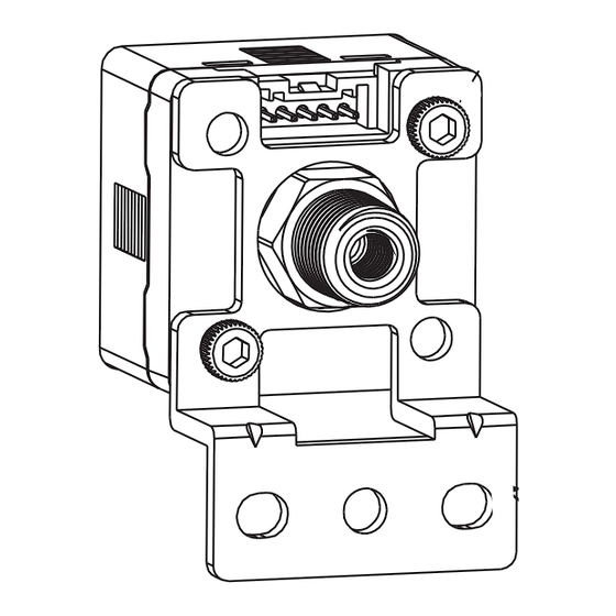
3.2 Mounting
M3
Mounting bracket
BT-12
M3
Mounting bracket
BT-13
Caution !
●
When mounting, always use the wrench on the metallic area near the pressure port. Never
Warning !
apply a wrench to the plastic body, it will damage the sensor.
Unrestricted
exhaust
●
Over tightening may cause damages to the port thread, mounting bracket and pressure
sensor. Under tightening may result loosen or leakage.
●
Apply pressure and power after installation and make necessary adjustments and inspect
any possible signs of leakage to ensure proper installation.
4
Specifications
4.1 Specifications
MODEL
Rated pressure range
Set pressure range
Withstand pressure
Fluid
kPa
kgf/cm
2
bar
Set pressure
resolution
psi
inHg
mmHg
Power supply voltage
Current consumption
Switch output
Repeatability(Switch output)
One point set mode
Hysteresis mode
Hysteresis
Window
comparator mode
Response time
Output short circuit protection
3 ½ digital, 7 segment LCD display ( Red / Green / Orange )
Display
Indicator accuracy
±2% F.S. ±1 digit (ambient temperature: 25 ±3°C)
Switch on indicator
Orange Indicator 1 : OUT1 & Orange Indicator 2 : OUT2
Enclosure
Ambient temp.
Range
Ambient humidity
Operation/Storage: 35 ~ 85% RH ( No condensation)
range
Withstand
Environment
voltage
Insulation
resistance
Total amplitude 1.5mm or 10G,10Hz-55Hz-10Hz scan
Vibration
for 1 minute, two hours each direction of X, Y and Z
Shock
100m/s
Temperature characteristic
±2.5% F.S. of detected pressure (25°C) at temp. Range of 0~50°C
Port size
Lead wire
Ø4 Oil-resistance cable ( PVC ) - 26 AWG ( 0.15 mm² ) - 5 cores
Weight
(With 2 meter cable and M8 4Pin male QD connector)
*1.Hysteresis value is adjustable within 1 ~ 8 digits for one point set mode and window comparator mode.
4.2 Output Circuit Wiring Diagrams
2 PNP+Copy function
BT-12
20
20
45
4.2
5
2
20
13
29.5
BT-13
5
20
20
20
45
29.5
2
20
Unit:mm
P43V-04-F3-QD
(Vacuum)
0.0 ~ -101.3 kPa
10.0 ~ -101.3 kPa
300 kPa
Filtered air, Non-corrosive / Non-flammable gas
0.1
0.001
0.001
0.01
0.1
1
12 to 24V DC ±10%, Ripple (P-P) 10% or less
≤ 40mA (With no load)
PNP: open collector 2 outputs
Max. load current: 125mA
Max. supply voltage: 24V DC
Residual voltage: ≤ 1.5V
±0.2% F.S. ±1 digit
Adjustable
(*1)
≤ 2.5ms
(chattering-proof function: 25ms, 100ms, 250ms,
500ms, 1000ms and 1500ms selections)
Yes
( Sampling rate : 5 times / sec. )
IP 40
Operation: 0 ~ 50°C, Storage:-10 ~ 60°C
( No condensation or freezing)
1000V AC in 1-min (between case and lead wire)
50MΩ (at 500V DC, between case and lead wire)
(10G), 3 times each in direction of X, Y and Z
2
F3: G1/8"(BSPP), M5
Approx. 80g
DC (+) (Brown)
OUT1(Black)
OUT2(White)
R
L
Copy function
R
(Orange)
L
DC (-) (Blue)
4.3 Ordering Information
P 4 3 V - 0 4 - F 3 - Q D
Pressure Range
V:Vacuum (10.0~-101.3kPa)
Output Specifications
04 :2 PNP+Copy function
Pressure Port
F3:G1/8"(BSPP), M5
Cable Length / Connector
QD:With 2 meter cable and M8 4Pin male QD connector
Optional Parts
BT-12:Mounting bracket
BT-13:Mounting bracket
4.4 Panel Description
mmHginHgpsibarkgfMPakPa
Lock Indicator
Output 1 Indicator
SET
(
)Button
Setting
(
)Button
Button
4.5 Dimensions
40.3
25.2
9
6
15
F3:G1/8"(BSPP), M5
21
30
25.2
30
Hex flat 12
4.6 Initial Setting Mode
kPa
Measure mode
SET
Press
SET
button for more than 3 seconds.
SET
kPa
OUT 1
Operating mode setting
(oPS)
SET
One point set
Hysteresis
mode
mode
SET
Use the
or
button to set OUT1 operating mode.
kPa
OUT 1
type setting
NO mode
NC mode
SET
SET
Use the
or
button to set OUT1 type.
kPa
OUT 2
Operating mode setting
oFF mode
(oPS)
One point set
Hysteresis
SET
mode
mode
SET
Use the
or
button to set OUT2 operating mode.
kPa
OUT 2
type setting
NO mode
NC mode
SET
Use the
or
button to set OUT2 type.
SET
kPa
Response time setting
2.5ms
25ms
100ms
SET
SET
Use the
or
button to select response time.
kPa
Display color setting
ON:Green
ON:Red
ON/OFF:
OFF:Red
OFF:Green
Green
SET
SET
Use the
or
button to set display color.
kPa
Unit setting
(kPa)
(kgf/cm
2
)
(bar)
SET
SET
Use the
or
button to set desired pressure unit.
kPa
Measure mode
SET
【 NOTE :】
*1. This setting mode will not display when output 2 is set to oFF.
Pressure Unit
Display Section
2 Color Main Display
Setting Mode
Sub-display Section
Output 2 Indicator
20
20
Unit:mm
Window comparator
mode
Window comparator
mode
(*1 )
250ms
500ms
1500ms
1000ms
ON/OFF:
Red
(psi)
(inHg)
(mmHg)
Advertisement

Related Manuals for PIAB P43V-04-F3-QD


Summary of Contents for PIAB P43V-04-F3-QD
- Page 1 BT-12 1.1 Identification Label 29.5 Each unit is identified by a label with identification information. For any communication with Optional Parts Piab AB or service centers always refer to the label information. BT-13 BT-12:Mounting bracket BT-13:Mounting bracket 1.2 Model Numbers Model number : P43V-04-F3-QD 4.4 Panel Description...
- Page 2 4.7 Advance Setting Mode 4.10 Pressure Setting Mode 4.14 Copy Function Setting ● ● Setting Condition 1: ● Setting Condition 2: Copy function setting can use the master sensor to copy the pressure value to the Measure mode slave sensors. OUT 1 mode setting:...
Need help?
Do you have a question about the P43V-04-F3-QD and is the answer not in the manual?
Questions and answers