Advertisement
Quick Links
Advertisement

Related Manuals for BLACK NOISE GOMA II

Summary of Contents for BLACK NOISE GOMA II
- Page 1 GOMA II Build Instructions V1.0...
-
Page 2: Warranty
B2 Header 1x2 01pcs B3 Exp Cable 01pcs B4 Power Cable 01pcs WARRANTY BLACK NOISE warrants the contents of this kit to be free of defects in materials or workmanship and to be conform with the specifications at the time of shipment for a period of two years from the date of purchase. -
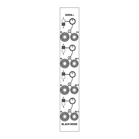
Page 3: Power Connector
CONNECTOR Power connector Place the 10-pin power connector on the back of the PCB as shown in image A. Solder one leg to one end of the connector and make sure the connector is properly positioned and aligned before soldering the opposite leg, then solder the remaining legs. - Page 4 LEDs & Spacers Place each LED spacer onto one of the bicolor LEDs as shown in image A. Slide the LED spacers along the LED leads and make sure they are firmly against the head of the LEDs. Place each LED with the spacers onto the PCB, make sure that the shorter lead of the LED aligns with the square hole on the LED footprint as shown in image C.
- Page 5 Components Place the 4 potentiometers as shown in image A. Place the 8 jack connectors as shown in image B. Place the 4 two-position switches as shown in image C. Make sure all the components are properly installed as shown in image D.
- Page 6 Faceplate Once all the components are in place, install the faceplate as shown in image A. Screw on the nuts for the 8 jack connectors as shown in image B. Flip the module over and solder all the components on the PCB as shown in image C.
- Page 7 +12V pins then -12V pins at each end of the connector. Your multimeter should not ring. Once you make sure that there is not short circuit, you can install the power cable included in the kit and connect you new GOMA II in you case.
Need help?
Do you have a question about the GOMA II and is the answer not in the manual?
Questions and answers