Table of Contents
Advertisement
Quick Links
PROJECT NAME
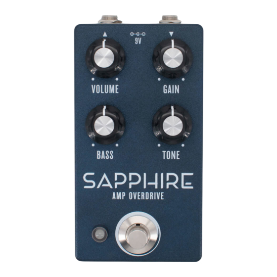
SAPPHIRE
BASED ON
®
BOSS
BD-2 Blues Driver
EFFECT TYPE
Overdrive
PROJECT SUMMARY
One of the most popular pedals in the BOSS lineup, it uses their distinctive "discrete op-amp" topology
to deliver an amp-like drive resembling vintage Fender tweed or blackface amps.
This documentation is for the kit version of the project. If you purchased the PCB by itself, please
use the
PCB-only version
are completely different due to the specialized parts and assembly methods used in the kit.
SAPPHIRE AMP OVERDRIVE
IMPORTANT NOTE
of the documentation instead. The circuit is the same, but the instructions
BUILD DIFFICULTY
Intermediate
DOCUMENT VERSION
1.0.0 (2024-06-01)
1
Advertisement
Table of Contents

Related Manuals for aion SAPPHIRE


Summary of Contents for aion SAPPHIRE
- Page 1 This documentation is for the kit version of the project. If you purchased the PCB by itself, please use the PCB-only version of the documentation instead. The circuit is the same, but the instructions are completely different due to the specialized parts and assembly methods used in the kit. SAPPHIRE AMP OVERDRIVE...
-
Page 2: Table Of Contents
21 Enclosure Layout: Main & Footswitch PCBs 22 Enclosure Layout: Input/Output PCB 23 Final Testing & Assembly 24 Schematic 25 Full Parts List 26 Troubleshooting Information 27 Support & Resale Terms 28 Legal Information & Document Revisions SAPPHIRE AMP OVERDRIVE... -
Page 3: Introduction
INTRODUCTION If this is your first pedal, welcome to the hobby and thank you for choosing Aion FX. You’ve just joined a community of over 40,000 people around the world with a passion for building homemade noise machines using obsolete electronics technologies, and we’re glad to have you! If you’ve done this before, it’s great to see you again and we’re confident you’ll find this build experience... - Page 4 NAME 220k 47uF 330k 100uF 470k MLCC Capacitors NAME 47pF (marked “470”) Diodes 100pF (marked “101”) NAME 220pF (marked “221”) 1N5817 100n (marked “104”) 1N914 Transistors NAME NAME 2N3906 JRC4558D 2N5088 8-pin socket 2SK209-GR with PCB adapter SAPPHIRE AMP OVERDRIVE...
- Page 5 Other 4-pin wire assembly header NAME LED bezel LED, white DC jack Input/output jack Mounting nut, jack, 0.54" Outer washer, jack, 0.6" Lock washer, jack, 0.5" (thin) Enclosure Enclosure screws PCB, main circuit PCB, footswitch PCB, input/output/DC SAPPHIRE AMP OVERDRIVE...
-
Page 6: Tools Needed
The tip should used to tighten the dress nut to avoid lot of pedals! be no more than 0.1” (2.5mm) wide. scratching or denting it (which can happen with metal tools). SAPPHIRE AMP OVERDRIVE... -
Page 7: Component Identification
Some voltage regulators The pins will be soldered to the also look like this. They may also look like this. adapter during kit assembly. have more than 8 legs. WIRE ASSEMBLY WIRE ASSEMBLY HEADER DC JACK LED BEZEL SAPPHIRE AMP OVERDRIVE... -
Page 8: Hardware Identification
MOUNTING NUT DRESS NUT LOCK WASHER DIAMETER: 0.36” / 9.1mm DIAMETER: 0.375” / 9.5mm DIAMETER: 0.4” / 10.1mm FOOTSWITCH MOUNTING NUT DRESS NUT LOCK WASHER DIAMETER: 0.6” / 15.2mm DIAMETER: 0.77” / 19.6mm DIAMETER: 0.6” / 15.2mm SAPPHIRE AMP OVERDRIVE... -
Page 9: Overview
6. Transistors 7. Electrolytic capacitors Not all of these component types are included in each kit, so skip them if they aren’t applicable. Some types of film capacitors are taller than electrolytics, so those can be done last. SAPPHIRE AMP OVERDRIVE... -
Page 10: Resistors
Turn the board upside-down to keep the components held in place while you solder. Don’t try to do all of the resistors at once. You’ll want to stop periodically flip the board and solder everything, then cut the leads using the wire snippers to make room for more. SAPPHIRE AMP OVERDRIVE... -
Page 11: Diodes
1N914 1N914 1N914 1N914 Next, you’ll populate the diodes. Diodes are polarized, so make sure to identify the polarity band (which indicates the “cathode”, or negative side) and match the band to the footprint on the PCB. SAPPHIRE AMP OVERDRIVE... -
Page 12: Sockets & Ics
ICs may have two different orientation marks: either a dot in the upper-left or a half-circle notch in the middle of the top side. Some ICs have both marks. This shows which way the IC should be rotated when inserting it into a socket (the socket also has a half-circle notch). SAPPHIRE AMP OVERDRIVE... -
Page 13: Transistors
Note that there is an extra “E” pad next to each transistor outline. These are only used for NOS Japanese transistors with different pinouts and should be ignored for the kit build. Install each transistor as shown in the silkscreen on the PCB. SAPPHIRE AMP OVERDRIVE... -
Page 14: Jfets
The component side of the PCB adapter should face toward the top of the PCB. As with the transistors, there is an extra “D” pad to the left of each JFET which is not used in the kit build. SAPPHIRE AMP OVERDRIVE... -
Page 15: Capacitors (Non-Polarized)
C4, C5, C6, C10, and C12 are blue MLCC capacitors taped to cardboard. For these, the value will be written on the cardboard. C24 (100n MLCC) is always yellow. It can be hard to read the code since it’s so small, so it’s easier to identify this one by color. SAPPHIRE AMP OVERDRIVE... -
Page 16: Wire Headers
They do fit pretty tightly in the holes, though, so press firmly. There’s also a 4-pin header on the I/O board that we will do in a later step. SAPPHIRE AMP OVERDRIVE... -
Page 17: Capacitors (Polarized)
If one leg is longer, this is the positive leg and it fits in the square pad. These are the last of the on-board components. Now is the time to go back to page 12 and insert the IC into the socket. SAPPHIRE AMP OVERDRIVE... -
Page 18: Footswitch Pcb
BLUE MARKING Once all three wire assemblies are soldered, set the footswitch PCB aside. We’ll solder the actual footswitch and LED in a later step. SAPPHIRE AMP OVERDRIVE... -
Page 19: Input/Output Pcb
PCB. There’s not a lot of clearance between the bottom of this board and the top of the main PCB once everything is in place, and you don’t want the pins to short against anything on accident. SAPPHIRE AMP OVERDRIVE... -
Page 20: Enclosure Layout: Panel Mounts
You’ll need to hold the bezel in place when OUTER WASHER tightening the nut. Be aware that the bezel is fairly MOUNTING NUT sharp. Try using a rubber band for grip instead of just pressing your finger against the bottom. SAPPHIRE AMP OVERDRIVE... -
Page 21: Enclosure Layout: Main & Footswitch Pcbs
However, Aion FX projects are designed to be extremely easy to remove from the enclosure for troubleshooting, with no desoldering required—so with these kits, it’s actually much easier to “box it before you rock it”. -
Page 22: Enclosure Layout: Input/Output Pcb
Note the use of two mounting nuts on each of the jacks, one inside and one outside. The inner nut acts as a spacer to set the DC jack flush with the outside of the enclosure. The inner nuts should be threaded as far down as they can go. MOUNTING NUT OUTER WASHER LOCK WASHER MOUNTING NUT 125B SAPPHIRE AMP OVERDRIVE... -
Page 23: Final Testing & Assembly
Last, just close the panel on the back using the four screws. Before that, though, grab a permanent marker and write your name and the completion date on the inside of the back panel. This is an accomplishment! SAPPHIRE AMP OVERDRIVE... -
Page 24: Schematic
1N5817 JRC4558D 47uF 100uF 100uF 47uF 100n 47uF 330k 2N3906 2SK209-GR Q2 Q3 47pF 47pF 2SK209-GR 100n 100k GAINB 250kA 150n OMIT 2N3906 Q5 Q6 100pF 100pF 2SK209-GR GAINA 250kA IC1B JRC4558D 2N5088 OMIT BASS 25kB 2N5088 SAPPHIRE AMP OVERDRIVE... -
Page 25: Full Parts List
2n2 film 56n film 2N5088 100pF MLCC 56n film 2N5088 Diodes Potentiometers Switches PART VALUE PART VALUE PART VALUE PART VALUE JRC4558D 1N5817 Gain 250kA dual 3PDT stomp 8-pin socket D2-D7 1N914 Tone 10kB Bass 25kB Volume 100kA SAPPHIRE AMP OVERDRIVE... -
Page 26: Troubleshooting Information
4.32 8.64 7.97 4.37 4.31 4.14 4.33 VOLTAGE VOLTAGE VOLTAGE 4.33 4.37 3.93 4.39 8.64 7.97 4.65 4.65 8.64 8.05 8.65 VOLTAGE VOLTAGE VOLTAGE VOLTAGE 4.39 8.64 8.65 9.38 8.06 3.81 4.20 9.33 8.64 3.38 3.65 8.65 SAPPHIRE AMP OVERDRIVE... - Page 27 “goop” the PCB or otherwise obscure the source. In other words: you don’t have to go out of your way to advertise the fact that you use Aion FX kits, but please don’t go out of your way to hide it.
- Page 28 These kits are intended to be built by the customer. Aion FX is not responsible for language that may be used by the customer in the marketing or resale of the finished product.
Need help?
Do you have a question about the SAPPHIRE and is the answer not in the manual?
Questions and answers