Table of Contents
Advertisement
Quick Links
Installation, Operation, and Maintenance
Water Source Heat Pump
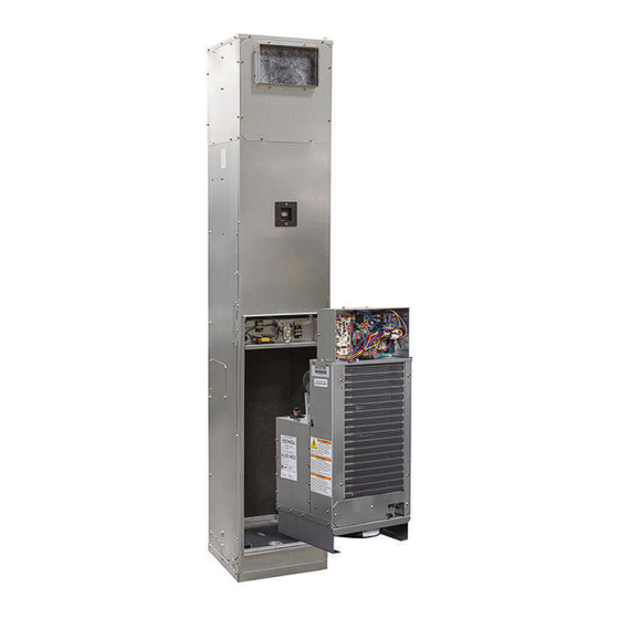
Axiom™ High Efficiency Vertical
Stack – GET
0.75 to 3 Tons – 60 Hz
Only qualified personnel should install and service the equipment. The installation, starting up, and servicing of heating, ventilating, and air-conditioning equipment
can be hazardous and requires specific knowledge and training. Improperly installed, adjusted or altered equipment by an unqualified person could result in death or
serious injury. When working on the equipment, observe all precautions in the literature and on the tags, stickers, and labels that are attached to the equipment.
June 2024
SAFETY WARNING
WSHP-SVX020A-EN
Advertisement
Table of Contents

Subscribe to Our Youtube Channel
Related Manuals for Trane Axiom WSHP Series


Summary of Contents for Trane Axiom WSHP Series
- Page 1 Installation, Operation, and Maintenance Water Source Heat Pump Axiom™ High Efficiency Vertical Stack – GET 0.75 to 3 Tons – 60 Hz SAFETY WARNING Only qualified personnel should install and service the equipment. The installation, starting up, and servicing of heating, ventilating, and air-conditioning equipment can be hazardous and requires specific knowledge and training.
- Page 2 (HCFCs). Not all refrigerants containing these compounds bump cap, fall protection, electrical PPE and arc have the same potential impact to the environment. Trane flash clothing). ALWAYS refer to appropriate advocates the responsible handling of all refrigerants.
- Page 3 Follow EHS Policies! This document and the information in it are the property of Trane, and may not be used or reproduced in whole or in Failure to follow instructions below could result in part without written permission. Trane reserves the right to death or serious injury.
-
Page 4: Table Of Contents
Table of Contents Model Number Description ....6 Ignition Sources in Unit ....19 Minimum Room Area Limits Vertical High-Rise Cabinet WSHP. - Page 5 Table of Contents Flow Checks ......39 General Operation ......42 Pressure .
-
Page 6: Model Number Description
Model Number Description Vertical High-Rise Cabinet WSHP Digits 1, 2, 3 — Unit Configuration Digit 14 — Open Digit Digit 23 — Unit Mounted Disconnect GET = High Efficiency Vertical High Rise Heat 0 = Open 0 = No Unit Mounted Switch Pump S = Special C = ON/OFF Switch... - Page 7 Model Number Description Digits 32 — Return Riser 0 = No Riser B = 1-inch Riser with Insulation C = 1.25-inch Riser with Insulation D = 1.5-inch Riser with Insulation E = 2-inch Riser with Insulation F = 2.5-inch Riser with Insulation G = 3-inch Riser with Insulation 2 = 1-inch Riser 3 = 1.25-inch Riser...
-
Page 8: Vertical High-Rise Chassis Wshp
Model Number Description Vertical High-Rise Chassis WSHP Digits 1, 2, 3 — Unit Configuration Digit 14 — Open Digit Digit 23 — Unit Mounted Disconnect GET = High Efficiency Vertical High Rise Heat 0 = Open 0 = No Unit Mounted Switch Pump C = ON/OFF Switch D = ON/OFF Switch with Fuses... -
Page 9: General Information
The The co-axial water-to-refrigerant heat exchanger for the Trane microprocessor board is factory wired to a terminal 0.75 ton through 3 tons equipment is constructed of copper strip to provide all necessary terminals for field connection. -
Page 10: Pre-Installation
Pre-Installation WARNING • Verify that the refrigerant charge has been retained during shipment by use of gauges. Schrader taps are Fiberglass Wool! located external to the cabinet on the 3/4 to 3 ton Exposure to glass wool fibers without all necessary equipment. - Page 11 Pre-Installation • Do not stack units. WSHP-SVX020A-EN...
-
Page 12: Dimensions And Weights
Dimensions and Weights WARNING Figure 1. Mechanical clearances Improper Unit Lift! Failure to properly lift unit in a LEVEL position could result in unit dropping and possibly crushing operator/technician which could result in death or serious injury, and equipment or property-only damage. -
Page 13: Dimensions And Weights With Standard
Dimensions and Weights Dimensions and Weights with Standard Base Figure 2. GET009-036 Table 2. Dimensional data - GET009-036 w/standard base A (inches) B (inches) C (inches) D (inches) E (inches) F (inches) 009-012 16 1/4 16 1/4 8 1/8 39 1/8 14 3/4 015-018 40 5/8... -
Page 14: Extended Base
Dimensions and Weights Dimensions and Weights with 6-inch Extended Base Figure 3. GET009-036 11" (279) FOR 86" (2184) CABINET HEIGHT 3" (76) FOR 94" (2388) CABINET HEIGHT 66” 10 3/4” 8 1/2” Table 3. Dimensional data - GET009-036 with 6-inch extended base A (inches) B (inches) C (inches) - Page 15 Dimensions and Weights Return Air (Hinged) Acoustical The opening through the wall for the door assembly must be centered with the return-air opening of the unit cabinet. Door with Standard Base For full installing instructions of the return-air acoustical door, see “Units Utilizing Hinged Acoustic Door The hinged acoustical door is recessed into the wall so that Assembly,”...
-
Page 16: Return Air (Hinged) Acoustical Door With 6-Inch Extended Base
Dimensions and Weights Return Air (Hinged) Acoustical The opening through the wall for the door assembly must be centered with the return-air opening of the unit cabinet. Door with 6-inch Extended Base For full installing instructions of the return-air acoustical door, see “Units Utilizing Hinged Acoustic Door The hinged acoustical door is recessed into the wall so that... -
Page 17: A2L Information
• To be repaired only by trained service At all times, Trane’s maintenance and service guidelines shall be followed. In in doubt, contact Trane technical personnel. support for assistance. • Do not puncture refrigerant tubing. -
Page 18: Leak Detection
Verify continuity of earth bonding. The recovery equipment shall be in good working order • Replace electrical components with Trane replacement with instructions available. Equipment shall be suitable for parts, or those meeting the same ratings and qualified the recovery of the flammable refrigerant. For specific for flame arrest protection, UL LZGH2 category. -
Page 19: Decommissioning
A2L Information • Ensure that the refrigerating system is earthed prior to the equipment are removed from site promptly and all charging the system with refrigerant. isolation valves on the equipment are closed off. • Label the system when charging is complete (if not 11. -
Page 20: Minimum Room Area Limits
A2L Information installed accessory electric heaters, gas heaters, relays, system. A ducted system requires circulation airflow and contactors) were evaluated during product UL listing. unless the smallest room it serves is larger than the adjusted A threshold. This product contains a leak Minimum Room Area Limits detection system if a circuit charge is greater than 3.91 lbs. -
Page 21: Leak Detection System
ANSI\ASHRAE Standard 15-2022, the sensor. Section 7.2.3.2. The refrigerant sensors do not need service. Use only Rooms that are connected by a mechanical ventilation Trane-approved sensors when replacement is required. system can be considered a single room area if the WSHP-SVX020A-EN... -
Page 22: Installation
Installation General Installation Checks 1. Verify the power supply complies with the unit nameplate specifications. The checklist below is a summary of the steps required to 2. Inspect all control panel components; tighten any loose successfully install a commercial unit. This checklist is connections. -
Page 23: Water Connection
Installation Figure 6. Stacking illustration Note: Take extra care as not to scrape or dent risers during positioning. The riser should fall approximately 2-inch into the 3-inch swage. This will allow for the variation in floor-to-floor dimensions, and keep the riser joints from bottoming out. -
Page 24: Field Installed Power Wiring
Installation Field Installed Power Wiring Route power wire to the cabinet control box through the factory installed conduit at the top of the unit cabinetry.The WARNING high voltage connection is made at the 1PB1 power block in the cabinet control box. Refer to the customer Proper Field Wiring and Grounding connection diagram that is shipped with the unit for specific Required! -
Page 25: Drywall Installation
Installation Drywall Installation Figure 9. Drywall installation for hinged acoustic door Before installing drywall around cabinet, cover the cabinet 3 1/2” ±3/8” supply and return openings with plastic or cardboard to 2“ X 4” STUD help prevent dust or construction debris from reaching unit SHEETROCK components. -
Page 26: Supply Air Ductwork
Installation 5. Secure the door frame to the side studs using the holes 9. Vacuum all dust and construction debris from unit after located in the door frame and field provided screws. cutting out supply/return openings. Note: If the gap between the door frame, and the side Supply Air Ductwork stud is over 1/16-inch, place a shim in between the door frame and the stud to prevent the door... -
Page 27: Supply Grille Installation
Installation Supply Grille Installation 4. Connect water coil pipe to the system riser with a flexible steel hose assembly. Table 9. Supply air opening size 5. Verify that the shut-off/balancing valve in the return line/ supply line are closed. Single Grille Two Grille Three Grille Discharge... -
Page 28: Using Antifreeze
WATER-SOURCE HEAT PUMP 2. Mount the thermostat, zone sensor or Trane® Air-Fi® WCI module on the finished drywall. TEMPORARY CONNECTION Thermostat/zone sensor connection shown below in the... -
Page 29: Psc Blower Motor Speed Retrofit
Installation Figure 17. Zone sensor connection Table 12. Deluxe controller diagnostic LEDs (continued) Color: Color: Controller Mode Green LED1 LED2 LED3 Manual Lockout (condensate FLASH overflow) Compressor Disable PSC Blower Motor Speed Retrofit PSC motors installed in the unit have multiple speed configurations. -
Page 30: Ecm Cfm Settings
Installation ECM CFM Settings Installation at higher altitudes may require an adjustment to the fan speed setting to achieve proper airflow. Use profile To adjust the CFM, disconnect the power to the unit. Set C or D to get lower airflow. If a lower CFM is needed, then the DIP switch located in the control box to the desired set DIP switch 4 to ON. - Page 31 Installation Table 15. PSC blower motor external static pressure without return air door (RAD) with filter (continued) External Static Pressure (in. of wg) Model 0.00 0.05 0.10 0.15 0.20 0.25 0.30 0.35 0.40 Speed Ducted Unit CFM KW CFM KW CFM KW CFM KW CFM KW CFM KW CFM KW CFM KW CFM KW High 652 0.191 634 0.187 616 0.183 598 0.179 579 0.175 558 0.17...
- Page 32 Installation Table 15. PSC blower motor external static pressure without return air door (RAD) with filter (continued) External Static Pressure (in. of wg) Model 0.90 0.95 1.00 1.05 1.10 Speed Ducted Unit CFM KW CFM KW CFM KW CFM KW CFM KW High GET009 High...
- Page 33 Installation Table 16. ECM Blower motor external static pressure without return air door (RAD) with filter (continued) External Static Pressure (in. of wg) Model Airflow 0.00 0.05 0.10 0.15 0.20 0.25 0.30 0.35 0.40 0.45 0.50 0.55 0.60 0.65 0.70 Profile 0.097 0.109...
-
Page 34: Electrical Data
Electrical Data Table 18. Electrical performance Minimum Maximum Comp RLA Comp Blower Motor Blower Motor Circuit Motor Option Model No. Unit Volts Total FLA Overcurrent (ea) Ampacity Protective Device 208/60/1 27.0 0.60 1/20 5.85 PSC Motor 230/60/1 27.0 0.60 1/20 5.85 265/60/1 22.0... -
Page 35: Pre-Start-Up
Operation, and Maintenance (BAS-SVX40*- ☐ Is the field wiring and circuit protection the correct size? EN) for Trane® Air-Fi® start-up. ☐ Is the low voltage control circuit wiring correct per the • See Symbio™ 400–B/500 Programmable... -
Page 36: Operating Pressures
Operating Pressures Use the form on “Start-Up Checklist and Log,” p. 40 to log airflow at the rated SCFM, entering air at 80.6°F DB, system and unit temperatures during start-up. 66.2 °F WB in cooling, 68°F DB in heating. (+)Heating data with 35°F EWT is based on the use of an anti-freeze General: There are many variables (airflow, air solution having a freezing point 20°F lower than the... - Page 37 Operating Pressures Table 19. Operating pressures (continued) Operating Data Cooling Heating Entering Water Flow Model Water Temp Suction Discharge Suction Discharge °F Air Temp Water Temp Water Temp Air Temp Pressure, Pressure, Pressure Pressure Drop °F DB Drop °F Rise °F Rise °F DB PSIG PSIG...
-
Page 38: Water Pressure Drop
Operating Pressures Table 19. Operating pressures (continued) Operating Data Cooling Heating Entering Water Flow Model Water Temp Suction Discharge Suction Discharge °F Air Temp Water Temp Water Temp Air Temp Pressure, Pressure, Pressure Pressure Drop °F DB Drop °F Rise °F Rise °F DB PSIG PSIG... -
Page 39: Water Volume
Operating Pressures Water Volume Table 22. Water volume The following table is provided for use in calculating glycol Water Side Water Side Water Side Unit requirements for the unit. Volume Cubic In. Volume Cubic Ft. Volume Gallons Table 21. Model flow option GPM press drop (feet) GET*009 18.7 0.011... -
Page 40: Start-Up
Start-Up Start-Up Checklist and Log (This form need not be returned to the factory unless requested during technical service support). Installing Contractor: Use this checklist to thoroughly check-out the system and units before and during start-up. Job Name: Model Number: Date: Serial Number: In order to minimize troubleshooting and costly system... -
Page 41: Maintenance
Maintenance Preventive Maintenance WARNING Hazardous Chemicals! Maintenance on the unit is simplified with the following preventive suggestions: Failure to follow this safety precaution could result in death or serious injury. Coil cleaning agents can be Filter maintenance must be performed to assure proper either acidic or highly alkaline and can burn severely operation of the equipment. -
Page 42: Troubleshooting
Troubleshooting WARNING to operate properly, refer to the troubleshooting checklist on Table 25, p. Hazardous Service Procedures! Failure to follow all precautions in this manual and on General Operation the tags, stickers, and labels could result in death or serious injury. The standard model is designed for indoor installation. - Page 43 Troubleshooting Table 25. Troubleshooting checklist (continued) Heating Cooling Problem Cause Correction Dirty filter Replace/clean Blower RPM too low Correct Loss of conditioned air due to Repair leaks leaks in ductwork Introduction of excessively hot Correct return-air Introduction of excessively cold Correct return-air Locate leak, repair and recharge by...
-
Page 44: Unit Wiring
FOR 600 VOLTS. DASHED LINE ENCLOSURE AND/OR DASHED DEVICE OUTLINES INDICATE COMPONENTS PROVIDED BY THE FIELD. SOLID LINES INDICATE WIRING BY THE TRANE CO. NUMBERS ALONG THE RIGHT SIDE OF THE SCHEMATIC DESIGNATE THE LOCATION OF THE CONTACTS BY LINE NUMBER. - Page 45 FOR 600 VOLTS. DASHED LINE ENCLOSURE AND/OR DASHED DEVICE OUTLINES INDICATE COMPONENTS PROVIDED BY THE FIELD. SOLID LINES INDICATE WIRING BY THE TRANE CO. NUMBERS ALONG THE RIGHT SIDE OF THE SCHEMATIC DESIGNATE THE LOCATION OF THE CONTACTS BY LINE NUMBER.
- Page 46 2 WIRE VALVE USE OPEN AND COM CONNECTION POINTS ATMOSPHERIC PRESSURE, AT 50% RELATIVE HUMIDITY, WITH ALL UTILITIES TURNED OFF, COMMUNICATION WIRE MUST BE TRANE PART NO. AND AFTER A NORMAL SHUTDOWN HAS 400-20-28, OR WINDY CITY OR CONNECT AIR OCCURRED.
- Page 47 2 WIRE VALVE USE OPEN AND COM CONNECTION POINTS ATMOSPHERIC PRESSURE, AT 50% RELATIVE HUMIDITY, WITH ALL UTILITIES TURNED OFF, COMMUNICATION WIRE MUST BE TRANE PART NO. AND AFTER A NORMAL SHUTDOWN HAS 400-20-28, OR WINDY CITY OR CONNECT AIR OCCURRED.
-
Page 48: Warranty
Warranty Standard Warranty Extended Warranty The standard water-source heat pump warranty is Trane The optional extended warranty is a second through fifth parts-only warranty, running 12-months from start-up, not year warranty. The time starts at the end of standard 1-year to exceed 18-months from shipment. - Page 49 Notes WSHP-SVX020A-EN...
- Page 50 Notes WSHP-SVX020A-EN...
- Page 51 Notes WSHP-SVX020A-EN...
- Page 52 For more information, please visit trane.com or tranetechnologies.com. Trane has a policy of continuous product and product data improvements and reserves the right to change design and specifications without notice. We are committed to using environmentally conscious print practices.
Need help?
Do you have a question about the Axiom WSHP Series and is the answer not in the manual?
Questions and answers