Table of Contents
Advertisement
Quick Links
ALL phases of this installation must comply with NATIONAL, STATE AND LOCAL CODES
IMPORTANT - This Document is customer property and is to remain with this unit. Please return to service
information pack upon completion of work.
These instructions do not cover all variations in systems or provide for every possible contingency to be met in connection with
the installation. Should further information be desired or should particular problems arise which are not covered sufficiently for the
purchaser's purposes, the matter should be referred to your installing dealer or local distributor.
Note: The manufacturer recommends installing only approved matched indoor and outdoor systems. All of the manufacture's split
systems are A.H.R.I. rated only with TXV/EEV indoor systems. Some of the benefits of installing approved matched indoor and
outdoor split systems are maximum efficiency, optimum performance and the best overall system reliability.
Table of Contents
Section 1. Safety ..................................................................................... 2
Section 2. Unit Location Considerations ............................................. 3
Section 3. Unit Preparation.................................................................... 4
Section 4. Setting the Unit ..................................................................... 4
Section 5. Refrigerant Line Considerations ......................................... 5
Section 6. Refrigerant Line Routing ..................................................... 6
Section 7. Refrigerant Line Brazing ...................................................... 7
Section 8. Refrigerant Line Leak Check ............................................... 8
Section 9. Evacuation and Servicing .................................................... 8
Section 10. Service Valves .................................................................... 9
Section 11. Electrical - Low Voltage ................................................... 10
Section 12. Electrical - High Voltage .................................................. 13
Section 13. Start Up.............................................................................. 14
Section 14. System Charge Adjustment............................................. 14
Section 15. Checkout Procedures and Troubleshooting .................. 18
Section 16. Defrost Control ................................................................. 19
Section 17. Troubleshooting ................................................................ 22
Section 18. Wiring Diagrams ............................................................... 24
Section 19. Pressure Curves ............................................................... 27
Section 20. Refrigerant Circuit (only for reference) .......................... 32
Installation and Operation Manual
Heat Pumps
A5HP5
88-A5HP5001-1B-EN
Advertisement
Table of Contents
Troubleshooting

Subscribe to Our Youtube Channel
Related Manuals for Trane A5HP5


Summary of Contents for Trane A5HP5
-
Page 1: Table Of Contents
88-A5HP5001-1B-EN Installation and Operation Manual Heat Pumps A5HP5 ALL phases of this installation must comply with NATIONAL, STATE AND LOCAL CODES IMPORTANT – This Document is customer property and is to remain with this unit. Please return to service information pack upon completion of work. -
Page 2: Section 1. Safety
Section 1. Safety WARNING WARNING Only qualified personnel should install and service the The appliance shall be stored in a room without equipment. The installation, starting up, and servicing continuously operating ignition sources (for examples: of heating, ventilating, and air-conditioning equipment open flames, an operating gas appliance or an operat- can be hazardous and requires specific knowledge ing electric heater). -
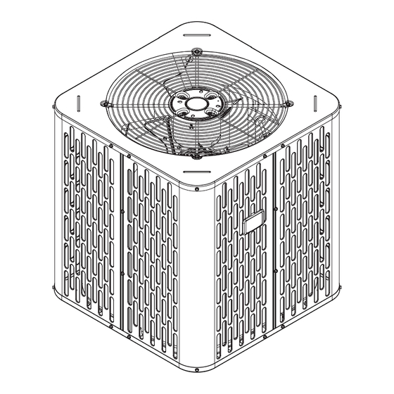
Page 3: Section 2. Unit Location Considerations
Section 2. Unit Location Considerations 2.1 Unit Dimensions and Weight Piping material, pipe routing, and installation shall include protection from physical damage in operation and service, and be in compliance with national and local codes and standards. All field joints shall be accessible for inspection prior to being covered or enclosed. -
Page 4: Section 3. Unit Preparation
2.4 Suggested Locations for Best Reliability Ensure the top discharge area is unrestricted for at least five (5) feet above the unit. Avoid Install Near Bedrooms Three (3) feet clearance must be provided in front of the control box (access panels) and any other side requiring service. -
Page 5: Section 5. Refrigerant Line Considerations
Section 5. Refrigerant Line Considerations 5.1 Refrigerant Line and Service Valve Connection Sizes Table 5.1 Rated Line Sizes Service Valve Connection Sizes Vapor Liquid Vapor Line Liquid Line Model Line Line Connection Connection A5HP5018A 5/16 5/16 A5HP5024A 5/16 5/16 A5HP5030A 5/16 5/16 A5HP5036A... -
Page 6: Section 6. Refrigerant Line Routing
5.5 Reuse Existing Refrigerant Lines CAUTION If using existing refrigerant lines make certain that all joints are brazed, not soldered. For retrofit applications, where the existing indoor evaporator coil and/or refrigerant lines will be used, the following precautions should be taken: •... -
Page 7: Section 7. Refrigerant Line Brazing
Wall Sealant Ductwork Insulation Vapor Line Isolator Line Set Isolation Through Wall DO NOT hang line sets from ductwork Section 7. Refrigerant Line Brazing 7.1 Braze The Refrigerant Lines STEP 1 - Remove caps or plugs. Use a deburing tool to debur the pipe ends. Clean both internal and external surfaces of the tubing using an emery cloth. -
Page 8: Section 8. Refrigerant Line Leak Check
3-4” from valve STEP 4 STEP 5 Section 8. Refrigerant Line Leak Check 8.1 Check For Leaks After completion of field piping for split systems, the field pipework shall be pressure tested with nitrogen and then vacuum tested prior to refrigerant charging. Important: Under no circumstances shall potential sources of ignition be used in the searching for or detection of refrigerant leaks. -
Page 9: Section 10. Service Valves
9.2 Servicing • If repairs must be made after system is charged, properly and safely remove or isolate refrigerant and purge the section of the system needing repair with nitrogen gas or oxygen-free nitrogen prior to opening the circuit. • The REFRIGERANT CHARGE shall be recovered into the correctly marked recovery cylinders. -
Page 10: Section 11. Electrical - Low Voltage
1/4 TURN ONLY COUNTERCLOCKWISE FOR FULL OPEN Unit Side POSITION of Service 3/16” Hex Wrench Valve Rolled Edge to VALVE STEM Captivate Stem Hex Headed UNIT SIDE Valve System OF VALVE PRESSURE TAP PORT Service Port GAS LINE CONNECTION Liquid Service Valve Gas Service Valve Section 11. - Page 11 With Furnace Outdoor Evaporator Coil MCB Furnace Thermostat Unit 24 VAC HOT 24 VAC Common 1. Units with pigtails require wirenuts for connections. Cap all unused wires. 2. For 24V control, connect factory supplied harness to circuit board at evaporator. COOL Complete all other wiring connections at the furnace 3.
- Page 12 11.3 Defrost Control - All Models except 036 Defrost controls have a selectable termination tem- perature. As shipped, defrost will terminate at 47°F. Defrost Board Detail For a higher termination temperature, cut Jumper J2 to achieve 70°F. Refer to the Defrost Control section in this document for more information.
-
Page 13: Section 12. Electrical - High Voltage
DEFROST TERMINATION TEMPERATURES OUTDOOR TERMINATION Defrost Board TEMPERATURE TEMPERATURE Detail >22°F 47°F SHIPPED JUMPER 2 10°F–22°F ODT + 25°F 6°F–10°F 35°F FRC_DFT CUT JUMP- >30°F 47°F TEST PINS ER 2 6°F–30°F 70°F <6°F 12 min. or 35°F every 3 hrs Section 12. -
Page 14: Section 13. Start Up
Section 13. Start Up 13.1 System Start Up STEP 1 - Ensure Sections 7 through 12 have been completed. STEP 2 - Set System Thermostat to OFF. STEP 3 - Turn on disconnect(s) to apply power to the indoor and outdoor units. STEP 4 - Wait one (1) hour before starting the unit if compressor crankcase heater accessory is used and the Outdoor Ambient is below 70ºF. - Page 15 STEP 2 - Determine the final subcooling value using R-454B REFRIGERANT CHARGING CHART total Line Length and Lift measured in STEP 1 and ° DESIGN SUBCOOLING ( the charts below. LIQUID For 018A - 060A Models: TEMP ( ° F) 018A Models LIQUID GAUGE PRESSURE (PSI) SUBCOOL CHARGING CHART CORRECTIONS TABLE (FOR LINE LENGTH AND RISE)
- Page 16 14.3 Charging the Unit STEP 1 - Attain Proper Gauge Pressure. Using the Standard R-454B Subcool Charging Chart, adjust refrigerant level to attain proper gauge pressure. Note: Use bubble point, per the included chart, for calculating subcooling. Add refrigerant in the Liquid Gauge Pressure is lower than the chart value 1.
- Page 17 14.4 Subcooling Charging Below 55º F Outdoor Temp. (In Heating Only) The Subcooling Charging method in cooling is not recommended below 55º F outdoor temperature. The recommended method of charging at outdoor temperatures below 55º F is weighing in the charge. Return when weather conditions permit charge verification through subcooling.
-
Page 18: Section 15. Checkout Procedures And Troubleshooting
STEP 3 - Check the liquid line temperature and liquid gauge pressure to obtain a minimum of 10º subcooling in heating mode. Measured Liquid Line Temp = __________ º F Liquid Gauge Pressure = __________ PSIG STEP 4 - Add charge if a minimum of 10º subcooling is not obtained with the nameplate charge plus additional charge previously added. -
Page 19: Section 16. Defrost Control
Section 16. Defrost Control Defrost Control The demand defrost control measures heat pump out- door ambient temperature with a sensor located outside the outdoor coil. A second sensor located on the outdoor coil is used to measure the coil temperature. The dif- ference between the ambient and the colder coil tem- perature is the difference or delta-T measurement. - Page 20 Table 1. Defrost Control Thermistor Table Table 2. DEMAND DEFROST QUICK SPECS THERMISTOR DEFROST ENABLED: TEMP °F TEMP °C RESISTANCE Volts DC Y = ON COIL TEM- ≤52 °F ≤52 °F (OHMS) PERATURE -15.00 -26.11 135976 2.50 DEFROST PERMIT: Y = ON COIL TEMPERA- ≤32 °F ≤32 °F...
- Page 21 c. Ambient sensor failure will initiate an Adaptive DEFROST Timed Limp Mode. This will be accompanied FAULT FAULT CONTROL by a 1 flash. The DFC will initiate defrost after DESCRIPTION CODES BEHAVIOR 60 minutes of accumulated heating runtime and force a defrost, which will terminate on Hard Lock Out (can coil temp.
-
Page 22: Section 17. Troubleshooting
Section 17. Troubleshooting Compressor fails to start Contactor check Is contactor engergized? Go To: Compressor won’t run (contacts closed) Wait 3 minutes and check contactor Check for 24 volts AC coil again across contactor coil Is voltage If applicable, is TDR present at input voltage Replace contactor... - Page 23 Compressor won’t run Contactor is closed Check for high voltage to contactor Check for open IOL Is high voltage present (Internal Overload) at T1 and T2 ? Check resistance of C to S and C to R Does the Check power resistance check Allow compressor supply from...
-
Page 24: Section 18. Wiring Diagrams
Section 18. Wiring Diagrams 88-A5HP5001-1B-EN... - Page 25 88-A5HP5001-1B-EN...
- Page 26 88-A5HP5001-1B-EN...
-
Page 27: Section 19. Pressure Curves
Section 19. Pressure Curves COOLING PERFORMANCE CAN BE CHECKED WHEN THE OUTDOOR TEMP IS ABOVE 65 DEG F. TO CHECK COOLING PERFORMANCE, SELECT THE PROPER INDOOR CFM, ALLOW PRESSURES TO STABILIZE. MEASURE INDOOR WET BULB TEMPERATURE, OUTDOOR TEMPERATURE, DISCHARGE AND SUCTION PRESSURES. ON THE PLOTS LOCATE OUTDOOR TEMPERATURE (1); LOCATE INDOOR WET BULB (2);... - Page 28 PRESSURE CURVES for A5HP5024A1 @SCFM @SCFM Heating Cooling INDOOR ENTERING INDOOR ENTERING WET BULB CURVES WET BULB CURVES TOP TO BOTTOM TOP TO BOTTOM 80, 70 AND 60 DEG F. 71, 67, 63 AND 59 DEG F. OUTDOOR T OUTDOOR TEMPERATURE (Degree F) OUTDOOR TEMPERATURE (Degree F) INDOOR ENTERING INDOOR ENTERING...
- Page 29 PRESSURE CURVES for A5HP5036A1 @SCFM @SCFM Heating Cooling 1100 1100 INDOOR ENTERING INDOOR ENTERING WET BULB CURVES WET BULB CURVES TOP TO BOTTOM TOP TO BOTTOM 80, 70 AND 60 DEG F. 71, 67, 63 AND 59 DEG F. OUTDOOR TEMPERATURE (Degree F) OUTDOOR TEMPERATURE (Degree F) INDOOR ENTERING INDOOR ENTERING...
- Page 30 PRESSURE CURVES for A5HP5048A1 @SCFM Heating @SCFM Cooling 1500 1500 INDOOR ENTERING INDOOR ENTERING WET BULB CURVES WET BULB CURVES TOP TO BOTTOM TOP TO BOTTOM 80, 70 AND 60 DEG F. 71, 67, 63 AND 59 DEG F. OUTDOOR TEMPERATURE (Degree F) OUTDOOR TEMPERATURE (Degree F) INDOOR ENTERING INDOOR ENTERING...
-
Page 31: Section 20. Refrigerant Circuit (Only For Reference)
Printed from D159360 About Trane and American Standard Heating and Air Conditioning Trane and American Standard create comfortable, energy efficient indoor environments for residential applications. For more information, please visit www.trane.com or www.americanstandardair.com The AHRI Certified mark indicates company participation in the AHRI Certification program. For verification of individual certified products, go to ahridirectory.org.
Need help?
Do you have a question about the A5HP5 and is the answer not in the manual?
Questions and answers