
Related Manuals for Soozier A61-045V02


Summary of Contents for Soozier A61-045V02
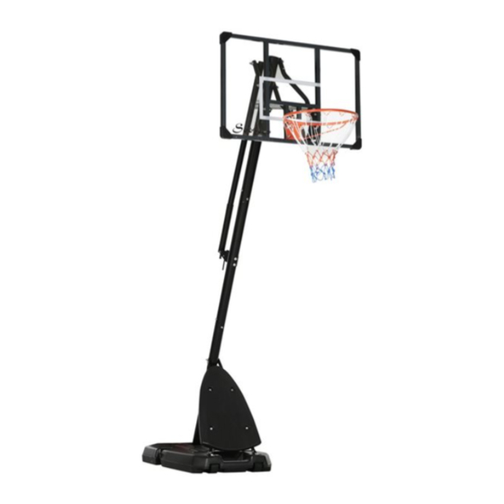
- Page 1 IN230200407V01_US_CA A61-045V02 Portable Basketball System IMPORTANT, RETAIN FOR FUTURE REFERENCE: READ CAREFULLY ASSEMBLY INSTRUCTION...
- Page 2 PACKING DETALS:TOTAL 2 BOXES BOX-1/2 Hardware Kit BOX-2/2...
-
Page 3: Safety Instructions
SAFETY INSTRUCTIONS FAILURE TO FOLLOW THESE WARNINGS MAY RESULT IN SERIOUS INJURY OR PROPERTY DAMAGE. To ensure safety, do not attempt to assemble this product without reading and following all instructions carefully. Check the entire box and inside all packing materials for parts and/or additional instruction material. Before beginning assembly, identify and inventory all parts and hardware using the parts and hardware lists and identi ers in this document. - Page 4 WARNING OWNERS MUST ENSURE THAT ALL PLAYERS KNOW AND FOLLOW THESE RULES FOR SAFE OPERATION OF THE SYSTEM. 1. Do Not allow children to move or adjust the system. 2. Always make sure adjustment knob is securely tightened before play. 3.
-
Page 5: Adjusting The System
TRANSPORTING THE PORTABLE BASE 1. Make sure the base is empty before moving. 2. Face the front of the base where the wheels are located and pull back on the pole until the unit is balanced on its wheels. 3. Move the unit to the desired location and carefully set it down. - Page 6 137*82*2.9mm M8*65mm M10*40mm M8*40mm M8*90mm M12*160mm M8*95mm...
- Page 7 M8*85mm 5*25mm 12* 16*18mm M12*160mm M8*25mm M6*45mm M12*55mm 25*12.5*1.0mm REQUIRED TOOLS 8*10mm 14*17mm 17*19mm...
- Page 8 STEP 1 Attach Bottom Pole (#1) to Base(#12) as shown. Secure the bottom pole to the base with 2 sets of Bolts and Washers (#16) and round plate (#24) as shown. STEP 2 Lock the Bottom Pole Braces (#4) to Base (#12) with 4 sets of Bolts, Washers, and Nuts (#34).
- Page 9 STEP 3 Attach the Bottom Pole Braces (#4) to Bottom pole (#1) with a set of Bolt, Washer and Nut (#19). M8*95mm STEP 4 Insert Axles (#22) into the Wheels (#21) as shown. Then press down over the wheels to snap the Axles in place.
- Page 10 STEP 5 Secure Cover (#33) to Bottom Pole Braces (#4) using 6 sets of Bolts, Washers and Nuts (#35). STEP 6 Secure Mounting Plate (#20) and Plate (#38) to Middle Pole (#2) with 2 sets of Bolts, Washers, and Nuts (#17) .
- Page 11 STEP 7 Secure Middle Pole (#2) to Bottom Pole (#1) with 2 sets of Bolts, Washers, and Nuts (#25). STEP 8...
- Page 12 STEP 9 Secure two Backboard Connecting Plates (#13) to Backboard (#9) with 4 sets of Bolts, Washers, and Nuts (#15). STEP 10 a. Attach two Short Connecting Tubes (#7) to Upper Parts of two Backboard Connecting Plates (#13) with 2 sets of Bolts, Washers, and Nuts (#36). b.
- Page 13 STEP 11 Attach Short Connecting Tubes (#7) and Long Connecting Tubes (#8) to the Top Pole (#3) as shown. Secure them with 2 sets of Bolts, Washers, and Nuts (#18). STEP 12 a. Screw the Lower Handle Bar (#5) to the Upper Handle Bar (#6). b.
- Page 14 c. Insert the Bolt (#31) through a Long Connecting Tube (#8), a Tube Washer (#23), the Uppe Handle Bar (#6), the other Tube Washer (#23) and the other Long Connecting Tube (#8) order. Then tighten the nut to lock them. d.
- Page 15 STEP 14 Please check all the bolts and nuts are all tightened after assembly. Always check the unit to ensure that the base is full of water or sand, and all ings and hardware are tight before each use. WARNING Sand is more recommended instead of water.
- Page 16 STEP 16 Please follow the below pictures to rotate the Crank Handle (#32) to adjust height.
-
Page 17: Instructions D'assemblage
IN230200407V01_US_CA A61-045V02 Panier de basketball portable IMPORTANT - CONSERVEZ CES INFORMATIONS POUR VOTRE CONSULTATION ULTÉRIEURE: LISEZ ATTENTIVEMENT INSTRUCTIONS D'ASSEMBLAGE... - Page 18 DÉTAILS DE L'EMBALLAGE : TOTAL 2 CARTONS CARTON -1/2 Hardware Kit CARTON -2/2...
- Page 22 137*82*2.9mm M8*65mm M10*40mm M8*40mm M8*90mm M12*160mm M8*95mm...
- Page 23 M8*85mm 5*25mm 12* 16*18mm M12*160mm M8*25mm M6*45mm M12*55mm 25*12.5*1.0mm REQUIRED TOOLS 8*10mm 14*17mm 17*19mm...
- Page 24 ÉTAPE 1 Fixez le montant inférieur (#1) à la base (#12) comme indiqué. Fixez le montant inférieur à la base avec 2 ensembles de boulons et rondelles (#16) et une plaque ronde (#24) comme indiqué. Matériel requis Ensemble boulon, rondelle M8*40mm QTÉ...
- Page 25 ÉTAPE 3 Fixez les entretoises du montant inférieur (#4) au montant inférieur (#1) avec un ensemble de boulon, rondelle et écrou (#19). Matériel requis Boulon, rondelle, écrou M8*95mm QTÉ : 1 ÉTAPE 4 Insérez les axes (#22) dans les roues (#21) comme indiqué. Appuyez ensuite sur les roues pour emboîter les axes en place.
- Page 26 ÉTAPE 5 Fixez le couvercle (#33) aux entretoises du montant inférieur (#4) en utilisant 6 ensembles de boulons, rondelles et écrous (#35). Matériel requis Boulon, rondelle et écrou M6*45mm QTÉ : 4 ÉTAPE 6 Fixez la plaque de montage (#20) et la plaque (#38) au montant central (#2) avec 2 ensembles de boulons, rondelles et écrous (#17).
- Page 27 ÉTAPE 7 Fixez le montant central (#2) au montant inférieur (#1) avec 2 ensembles de boulons, rondelles et écrous (#25). Matériel requis Boulon, rondelle et écrou M8*85mm QTÉ : 2 ÉTAPE 8 Matériel requis Ensemble boulon, rondelle et vis M8*60mm QTÉ : 2 Ensemble boulon, rondelle et vis M8*90mm QTÉ...
- Page 28 ÉTAPE 9 Fixez deux plaques de connexion de panneau (#13) au panneau (#9) avec 4 ensembles de boulons, rondelles et écrous (#15). Matériel requis Boulon, rondelle, écrou M10*40mm QTÉ : 4 ÉTAPE 10 a.Attachez deux tubes de connexion courts (#7) aux parties supérieures des deux plaques de connex- ion de panneau (#13) avec 2 ensembles de boulons, rondelles et écrous (#36).
- Page 29 ÉTAPE 11 Fixez les tubes de connexion courts (#7) et les tubes de connexion longs (#8) au montant supérieur (#3) comme indiqué. Fixez-les avec 2 ensembles de boulons, rondelles et écrous (#18). Matériel requis Boulon, rondelle, écrou M12*160mm QTÉ : 2 ÉTAPE 12 a.Vissez la barre de poignée inférieure (#5) à...
- Page 30 c.Insérez le boulon (#31) à travers un tube de connexion long (#8), une rondelle de tube (#23), la barre de poignée supérieure (#6), l'autre rondelle de tube (#23) et l'autre tube de connexion long (#8) dans l'ordre. Serrez ensuite l'écrou pour les verrouiller. d.Fixez le montant supérieur (#3) au montant central (#2) avec 2 ensembles de boulons, rondelles et écrous (#25).
- Page 31 ÉTAPE 14 Veuillez vérifier que tous les boulons et écrous sont bien serrés après l'assemblage. Vérifiez toujours l'unité pour vous assurer que la base est pleine d'eau ou de sable, et que tous les accessoires et matériels sont bien serrés avant chaque utilisation. AVERTISSEMENT Le sable est plus recom- mandé...
- Page 32 ÉTAPE 16 Veuillez suivre les images ci-dessous pour tourner la manivelle (#32) afin d'ajuster la hauteur. Remplissez entièrement la base avec de l'eau.
Need help?
Do you have a question about the A61-045V02 and is the answer not in the manual?
Questions and answers