Table of Contents
Advertisement
Quick Links
Advertisement
Table of Contents

Related Manuals for Ross openGear FDR-6603


Summary of Contents for Ross openGear FDR-6603
- Page 1 Ross Video Limited FDR-6603 Dual Channel Optical Receiver User Manual...
- Page 2 The material in this manual is furnished for informational use only. It is subject to change without notice and should not be construed as commitment by Ross Video Limited. Ross Video Limited assumes no responsibility or liability for errors or inaccuracies that may appear in this manual.
- Page 3 Important Regulatory and Safety Notices Before using this product and any associated equipment, refer to the “Important Safety Instructions” listed below to avoid personnel injury and to prevent product damage. Products may require specific equipment, and/or installation procedures to be carried out to satisfy certain regulatory compliance requirements.
- Page 4 Notice — Changes or modifications to this equipment not expressly approved by Ross Video Limited could void the user’s authority to operate this equipment. CANADA This Class “A” digital apparatus complies with Canadian ICES-003.
- Page 5 Important Laser Safety Measures and Notices Before using this product and any associated equipment, refer to the sections below so as to avoid personnel injury and to prevent product damage. For further safety information when using fiber products, consult the following publications: •...
- Page 6 The crossed-out wheeled bin symbol invites you to use these systems. If you need more information on the collection, reuse, and recycling systems, please contact your local or regional waste administration. You can also contact Ross Video for more information on the environmental performances of our products.
- Page 7 Company Address Ross Video Limited Ross Video Incorporated 8 John Street P.O. Box 880 Iroquois, Ontario Ogdensburg, New York Canada, K0E 1K0 USA 13669-0880 General Business Office: (+1) 613 • 652 • 4886 Fax: (+1) 613 • 652 • 4425 Technical Support: (+1) 613 •...
-
Page 9: Table Of Contents
Contents Introduction Overview..........................1-2 Features........................1-2 FDR-6603 Functional Block Diagrams ................1-3 Documentation Terms and Conventions................1-4 Installation Before You Begin ........................ 2-2 Static Discharge..................... 2-2 Unpacking......................2-2 Working with Fiber Optic Connectors ..............2-2 Installing the FDR-6603 ...................... 2-3 Rear Modules for the FDR-6603................ - Page 10 ii • Contents FDR-6603 User Manual (Iss. 02)
-
Page 11: Introduction
Congratulations on choosing an openGear FDR-6603 Dual Channel Optical Receiver. Your FDR-6603 is part of a full line of Digital Products within the openGear Terminal Equipment family of products, backed by Ross Video's experience in engineering and design expertise since 1974. -
Page 12: Overview
Overview The FDR-6603 provides the ability to transport digital video baseband signals over a fiber optic link, allowing for longer transport distances. SDI outputs are reclocked providing excellent jitter and return loss specifications. Both cards support serial digital data rates from 270Mbps up to 2.98Gbps (1080p). -
Page 13: Fdr-6603 Functional Block Diagrams
FDR-6603 Functional Block Diagrams This section provides a functional block diagrams that outlines the signal flow of the FDR-6603 . Figure 1.1 FDR-6603 with a Full Rear Module — Simplified Block Diagram Figure 1.2 FDR-6603 with a Split Rear Module — Simplified Block Diagram (Single Card only) FDR-6603 User Manual (Iss. -
Page 14: Documentation Terms And Conventions
Documentation Terms and Conventions The following terms and conventions are used throughout this manual: • “Frame” refers to DFR-8321 series frame that houses the FDR-6603, as well as any openGear frames. • All references to the DFR-8321 series frame includes all versions of the DFR-8321 series frames and any available options unless otherwise noted. -
Page 15: Installation
Installation In This Chapter This chapter provides instructions for installing the Rear Module(s) for the FDR-6603, installing a card into the frame, cabling details, and updating the software. The following topics are discussed: • Before You Begin • Installing the FDR-6603 •... -
Page 16: Before You Begin
Unpacking Unpack each card you received from the shipping container and ensure that all items are included. If any items are missing or damaged, contact your sales representative or Ross Video directly. Working with Fiber Optic Connectors Keep the following in mind when working with fiber optic connectors: •... -
Page 17: Installing The Fdr-6603
Installing the FDR-6603 This section outlines how to install a Rear Module in a DFR-8321 series frame. However, the specific Rear Module you need to install depends on your application. Caution — Never attempt to look down the barrel of a connected fiber or device transmitting an optical signal. -
Page 18: Installing A Card
Installing a Card Use the following procedure to install a card in a DFR-8321 series frame: 1. Locate the Rear Module you installed in the procedure “Installing a Rear Module”. 2. Ensure that the Rear Module is one of the required models for the FDR-6603. You must use either a Full Rear Module (8320AR-044) or a Split Rear Module (8320AR-045). -
Page 19: Cabling
Cabling This section provides information for connecting cables to the installed Rear Modules on the DFR-8321 series frames. Connect the input and output cables according to the following sections. The optical connector used to mate the card to the rear module is designed for blind mate optical connections. -
Page 20: Software Upgrades
Performing Software Upgrades Use the following procedure to upgrade the software on a card: 1. Contact Ross Technical Support for the latest software version file. 2. Display the Device View of the card by double-clicking its status indicator in the Basic Tree View. -
Page 21: User Controls
User Controls In This Chapter This chapter provides a general overview of the user controls available on the FDR-6603. The following topics are discussed: • Card Overview • Control and Monitoring Features FDR-6603 User Manual (Iss. 02) User Controls • 3–1... -
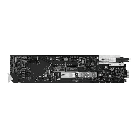
Page 22: Card Overview
Card Overview This section provides a general overview of the card components. For information on the LEDs available on the card-edge, refer to the section “Control and Monitoring Features” on page 3-4. Figure 3.1 FDR-6603 — Components 1) Rx Power LEDs - Channel A 5) Select Switch - Channel A (SW1) 9) Select Switch - Channel B (SW2) 2) Card Control (JP1) - Page 23 5. Select Switch - Channel A (SW1) Use SW1 to set the reclocking rate of the card for Channel A. Pressing SW1 cycles through the following options: • AUTO — This option enables automatic rate detection on the card. It will automatically lock to input at any supported data rate (270Mbps, 1.5Gbps, or 3Gbps).
-
Page 24: Control And Monitoring Features
Control and Monitoring Features This section provides information on the LEDs for the FDR-6603. Refer to Figure 3.2 for the location of the LEDs. For information on the Rx Power LEDs, refer to the section “Rx Power LEDs on the FDR-6603” on page 3-6. Figure 3.2 FDR-6603 Card-edge Controls 3–4 •... -
Page 25: Status Leds On The Fdr-6603
Status LEDs on the FDR-6603 The front-edge of the card has LED indicators for alarms, and communication activity. Basic LED displays and descriptions are provided in Table 3.1. Table 3.1 LEDs on the FDR-6603 Color Display and Description When lit green, this LED indicates that the card is functioning Green normal and that no anomalies have been detected. - Page 26 Rx Power LEDs on the FDR-6603 Table 3.2 provides information on the Rx Power LEDs located on the card. These LEDs indicate the input optical power as reported by the card optical module. Table 3.2 Rx Power LEDs Rx Power LEDs Description The input optical power is greater than -6dBm The input optical power is between -6dBm and -9dBm...
-
Page 27: Menus
Menus In This Chapter This chapter provides a summary of the menus available for the FDR-6603. The following topics are discussed: • Overview • Status Tabs • Setup Menus • Alarms Menus FDR-6603 User Manual (Iss. 02) Menus • 4–1... -
Page 28: Overview
Overview The FDR-6603 supports two types of monitoring and control: SNMP or DashBoard. SNMP Monitoring and Control The MFC-8300 Series Network Controller card in the DFR-8321 series frame provides optional support for remote monitoring of your frame and using the Simple Network Management Protocol (SNMP), which is compatible with many third-party monitoring and control tools. -
Page 29: Status Tabs
Status Tabs This section summarizes the Status tab parameters available in DashBoard. The Status tabs provide read-only information such as software revision issue, hardware status, and power consumption. Signal Tab Table 4.1 summarizes the read-only information, such as channel status and optical module status, displayed in the Signal tab. -
Page 30: Hardware Tab
Table 4.3 summarizes the read-only information displayed in the Product tab. Table 4.3 Product Tab Items Tab Title Item Parameters Description Product FDR-6603 Supplier Ross Video Ltd. Board Rev Product (Read-only) Board S/N ###### Indicates the card serial number Rear Module Indicates the rear module installed Software Rev ##.##... -
Page 31: Setup Menus
Setup Menus Table 4.4 summarizes the Setup Menu options available in DashBoard. Table 4.4 Setup Menu Items Menu Title Item Parameters Description The card automatically detects the Auto* incoming data rate for the specified channel The card does not reclock the input for the Bypass specified channel Reclock Rate... -
Page 32: Alarms Menus
Alarms Menus Table 4.5 summarizes the Alarms Menu options available in DashBoard. Table 4.5 Alarms Menu Items Menu Title Item Parameters Description HW Status field reports when the power Selected* consumption of the SFP module is not in Alarm on Abnormal range (high/low) Power Cleared... -
Page 33: Specifications
Specifications In This Chapter This chapter includes the technical specifications for the FDR-6603. Note that specifications are subject to change without notice. The following topics are discussed: • FDR-6603 Technical Specifications FDR-6603 User Manual (Iss. 02) Specifications • 5–1... -
Page 34: Fdr-6603 Technical Specifications
FDR-6603 Technical Specifications This section provides the technical specifications for the FDR-6603. Table 5.1 FDR-6603 Technical Specifications Category Parameter Specification Number of Inputs SMPTE Standards Accommodated SMPTE 259M-C, SMPTE 292M, SMPTE 424M Operating Wavelength Range 1260nm to 1620nm • -3dBm to -18dBm @ 2.97Gbps Input Power Operating Range (Color Bars) •... -
Page 35: Service Information
Service Information In This Chapter This chapter contains the following sections: • Troubleshooting Checklist • Warranty and Repair Policy FDR-6603 User Manual (Iss. 02) Service Information • 6–1... -
Page 36: Troubleshooting Checklist
Bootload Button In the unlikely event of a complete card failure, you may be instructed by a Ross Technical Support specialist to perform a complete software reload on the card. -
Page 37: Warranty And Repair Policy
In the event that your FDR-6603 proves to be defective in any way during this warranty period, Ross Video Limited reserves the right to repair or replace this piece of equipment with a unit of equal or superior performance characteristics. - Page 38 Notes:...
- Page 39 Notes:...
- Page 40 P.O. Box 880, Ross Video Incorporated Ogdensburg, New York, USA 13669-0880 Visit Us Please visit us at our website for: • Company information • Related products and full product lines • On-line catalog • News • Testimonials Ross Part Number: 6603DR-004-02...
Need help?
Do you have a question about the openGear FDR-6603 and is the answer not in the manual?
Questions and answers