Table of Contents
Advertisement
Quick Links
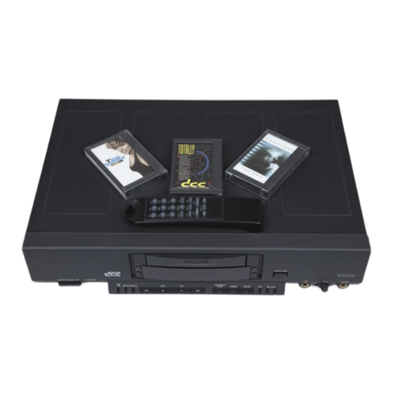
DIGITAL COMPACT CASSETTE RECORDER
(@
6
THIRD GENERATION DCC (reference set: DCC951)
Service
Service
Service
COMPACT CASSETTE
CONTENTS
PAGE
IMtTOUUCHONS
24.2 Sante
ALO
ea
PE
EY
HE
ee
ee
5
UoGENERAL
0.5.2 sateen ete a tetim analy
Sinaey Bete aye BRD
Bas
9
1.1
DCC recorders third generation. .................0...
9
1.2
Block diagram of the DCC Digital Unit Module (DDU)
...
12
1.3
Block diagram DCC951_
www ee
eee
13
2 TAPE DRIVE PART MECHANICAL
....................
17
2c:t
"Head support
ob ad ode
od bn be
ERAS
eG
oe
17
2.2
Command gearwheel..............
0200002
eee
19
2.3
Azimuth adjustment ..........
0.00.00.
2022
eee
21
2.4
Write current adjustment.
....................005.
23
3 TAPE DRIVE PART ELECTRICAL
....................
24
3.1
Read/Write board
........
0.0.0.0...
cee
ee
24
3:2
Digital'board:
2...
eee
Re EW
ae ee
ee
35
3.3
Tape drive control board
...............
000000085
52
4 SINTEREAGE®
sosalsn cae
g Se adade 480445404428
Los
69
4.1
Power Supply
...........
0.2.0.0. 02: e eee eee
69
4:2.
hf QurbD Gard \ 03
Phy
eae
Pe ete
ee
ees
4
es
69
4.3
Control & Display Board
.....................05.
69
5 uP SERVICE MODE .............
00.00.
es
74
5.1
Start service mode
..........
0.0... 0. eee
eee
74
5.2
Switches Test Mode
............
0... 000.00
ee
74
5.3
DCC Digital Unit Test Mode
...................0..
74
5.4
The User Test Mode
.............
2.0.00 00 0. eee
78
6 ABBREVIATIONS
...........0
0.0.00
ee
ee
80
Copyright: Philips Sound & Vision B.V. The Netherlands, Service BG Audio, SFF3.
Published by Philips Sound & Vision
Printed in The Netherlands
©Copyright reserved
Subject to modification
GB
4822
725 24755
ao
PHILIPS
Advertisement
Table of Contents


Need help?
Do you have a question about the 900 Series and is the answer not in the manual?
Questions and answers