Advertisement
Available languages
Available languages
Quick Links
EVCO S.p.A. | EVD Web | Instruction sheet ver. 1.0 | Code 104DWEBA103 | Page 1 of 2 | PT 13/23
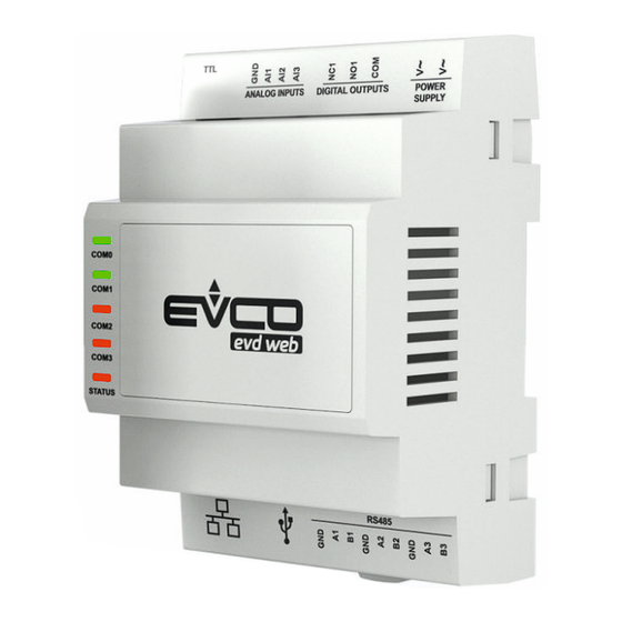
EVD Web
EN
ENGLISH
-
power supply 115... 230 VAC
-
clock
-
3 analogue inputs (Pt 1000)
-
Ethernet port
-
3 RS-485 MODBUS master ports
-
TTL MODBUS port
-
Micro-USB port
1
MEASUREMENTS AND INSTALLATION
Measurements in mm (inches). To be fitted on a DIN rail, in a control panel.
To install the device operate as shown in pictures 1 and 2.
To remove the device, first remove any screw-in removable terminal blocks mounted in the
lower part, then operate as shown in pictures 3 and 4.
To install the device again press down the clip before.
INSTALLATION PRECAUTIONS
-
ensure that the working conditions are within the limits stated in the TECHNICAL
SPECIFICATIONS section
do not install the device close to heat sources, equipment with a strong magnetic field,
-
in places subject to direct sunlight, rain, damp, excessive dust, mechanical vibrations
or shocks
-
in compliance with safety regulations, the device must be installed properly to ensure
adequate protection from contact with electrical parts. All protective parts must be
fixed in such a way as to need the aid of a tool to remove them
IoT gateways for EPoCA
2
ELECTRICAL CONNECTION
N.B.
- use cables of an adequate section for the current running through them
- The power supplies of the controllers connected to the RS-485 networks must be
galvanically isolated from each other
- to reduce any electromagnetic interference connect the power cables as far away
as possible from the signal cables and, if necessary, connect to RS-485 MODBUS
networks using a twisted pair
- the maximum number of controllers that can be connected to each RS-485 port is
6
- compatibility with the EPoCA® cloud platform of the connected controllers depends
on the type of controller: consult the document "EPoCA - List of compatible control-
lers" available on the website www.evco.it, which can also be accessed by scanning
the following QR code:
2.1
Connectors
symbol 1
Ethernet port
symbol 2
Micro-USB port
RS485
N.
DESCRIPTION
GND
reference (GND) RS-485 MODBUS master port 1
A1
signal + RS-485 MODBUS master port 1
B1
signal - RS-485 MODBUS master port 1
GND
reference (GND) RS-485 MODBUS master port 2
A2
signal + RS-485 MODBUS master port 2
B2
signal - RS-485 MODBUS master port 2
GND
reference (GND) RS-485 MODBUS master port 3
A3
signal + RS-485 MODBUS master port 3
B3
signal - RS-485 MODBUS master port 3
POWER SUPPLY
N.
DESCRIPTION
V~
device power supply (115... 230 VAC)
V~
device power supply (115... 230 VAC)
DIGITAL OUTPUTS
N.
DESCRIPTION
NC1
reserved
NO1
reserved
COM
reserved
ANALOG INPUTS
N.
DESCRIPTION
GND
reference (GND)
AI1
analogue input 1 (for Pt 1000 probes)
AI2
analogue input 2 (for Pt 1000 probes)
AI3
analogue input 3 (for Pt 1000 probes)
TTL
TTL MODBUS port
PRECAUTIONS FOR ELECTRICAL CONNECTION
if using an electrical or pneumatic screwdriver, adjust the tightening torque
-
if the device has been moved from a cold to a warm place, the humidity may have
-
caused condensation to form inside. Wait about an hour before switching on the power
make sure that the supply voltage, electrical frequency and power are within the set
-
limits. See the section TECHNICAL SPECIFICATIONS
-
disconnect the power supply before doing any type of maintenance
-
do not use the device as safety device
-
for repairs and for further information, contact the EVCO sales network
3
OPERATION
Look at the user manual available on the website www.evco.it.
4
TECHNICAL SPECIFICATIONS
Container
grey, self-extinguishing
Category of heat and fire resistance
D
Measurements
4 DIN modules: 71.0 x 110.0 x 60.0 mm
(2 13/16 x 4 5/16 x 2 3/8 in)
Mounting methods for the control device
to be fitted on a DIN rail, in a control panel
Degree of protection provided by the cover-
IP40
ing
Connection method
screw
terminal
blocks
for
wires
up
to
screw
1.5 mm²
2.5 mm²
RJ45 F telephone connector
Pico-Blade connector
Micro-USB connector
Maximum permitted length for connection cables
power supply: 10 m (32.8 ft)
analogue inputs: 10 m (32.8 ft)
RS-485 MODBUS master port: 1,000 m
Micro-USB port: 1 m (3,28 ft)
(3,280 ft)
To wire the device it is recommended to use the connection kit CJAV74 (to be ordered sepa-
rately)
Operating temperature
from 0 to 60 °C (from 32 to 140 °F)
Storage temperature
from -20 to 70 °C (from -4 to 158 °F)
Operating humidity
relative humidity without condensate from 5
to 95%
Pollution status of the control device
2
Compliance
RoHS 2011/65/CE
WEEE 2012/19/EU
REACH (EC) Regulation no. 1907/2006
EMC 2014/30/UE
LVD 2014/35/UE
Power supply
115... 230 VAC (+10 % -15 %), 50/60 Hz
(±3 Hz), max. 4 VA, 2 W
Earthing methods for the control device
none
®
system
Rated impulse-withstand voltage
Over-voltage category
Software class and structure
Clock
Clock drift
Clock battery autonomy in the absence of a
power supply
Clock battery charging time
Analogue inputs
Pt 1000 probes
The device guarantees:
- reinforced insulation between live parts and SELV circuits
- basic insulation between live parts of opposite polarity (line-neutral)
Communications ports
1 Ethernet port
1 TTL MODBUS port
terminal
blocks
for
wires
up
to
2.5 KV
II
A
incorporated (with secondary lithium battery)
≤ 30s/month at 25°C (77 °F)
> 6 months at 25 °C (77 °F)
24h (the battery is charged by the power
supply of the device)
3 for Pt 1000 probes
Sensor type
1 K @ 0 °C, 32 °F
Measurement field
from -100 to 600 °C (from -148 to 1.112 °F)
Resolution
0.1 °C (1 °F)
Accuracy
±2.5 °C
3 RS-485 MODBUS master ports
1 Micro-USB port
Advertisement

Related Manuals for Evco EVD Web


Summary of Contents for Evco EVD Web
- Page 1 EVCO S.p.A. | EVD Web | Instruction sheet ver. 1.0 | Code 104DWEBA103 | Page 1 of 2 | PT 13/23 EVD Web ® IoT gateways for EPoCA system ELECTRICAL CONNECTION Rated impulse-withstand voltage 2.5 KV Over-voltage category N.B. Software class and structure...
- Page 2 EVCO S.p.A. | EVD Web | Instruction sheet ver. 1.0 | Code 104DWEBA103 | Page 2 of 2 | PT 13/23 ITALIANO simbolo 1 alimentazione 115... 230 VAC Porta Ethernet orologio incorporato 3 ingressi analogici (Pt 1000) simbolo 2 porta Ethernet...
Need help?
Do you have a question about the EVD Web and is the answer not in the manual?
Questions and answers