
Related Manuals for ASROCK K8UPGRADE-NF3


Summary of Contents for ASROCK K8UPGRADE-NF3
-
Page 1: User Manual
K8Upgrade-NF3 User Manual Version 1.1 Published July 2006 Copyright©2006 ASRock INC. All rights reserved. 1 1 1 1 1... - Page 2 (including damages for loss of profits, loss of business, loss of data, interruption of business and the like), even if ASRock has been advised of the possibility of such damages arising from any defect or error in the manual or product.
-
Page 3: Table Of Contents
Serial ATA (SATA) Hard Disks Installation ........ 19 Realtek Audio Driver Installation For Windows ME ....19 Installing Windows 2000 / XP / XP 64-bit With RAID Functions. 20 2.10 Installing Windows 2000 / XP / XP 64-bit Without RAID Functions ................. - Page 4 4 . 4 . 4 . 4 . 4 . Software Support Software Support Software Support Software Support ..........................................39 Software Support ........... Install Operating System ............39 Support CD Information ............. 39 4.2.1 Running Support CD ............39 4.2.2 Drivers Menu ..............
-
Page 5: Introduction Introduction
ASRock’s commit- ment to quality and endurance. In this manual, chapter 1 and 2 contain introduction of the motherboard and step-by- step guide to the hardware installation. Chapter 3 and 4 contain the configuration guide to BIOS setup and information of the Support CD. -
Page 6: Specifications
Specifications Specifications Specifications Specifications Specifications Platform: ATX Form Factor: 12.0-in x 7.5-in, 30.5 cm x 19.1 cm CPU: 754-Pin Socket Supporting advanced 64-bit AMD Athlon and 32-bit / 64-bit Sempron Processors Supports AMD’s Cool ‘n’ Quiet Technology (see CAUTION 1) - Page 7 This motherboard supports Untied Overclocking Technology. During overclocking, FSB enjoys better margin due to fixed AGP/PCI buses. In other words, CPU FSB is untied during overclocking, but AGP and PCI buses are in the fixed mode so that FSB can operate under a more stable overclocking environment.
-
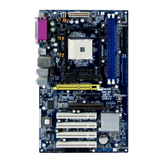
Page 8: 1.3 Motherboard Layout
CPU Heatsink Retention Module Game Port Header (GAME1) CPU Fan Connector (CPU_FAN1) Front Panel Audio Header (AUDIO1) 184-pin DDR DIMM Slots (DDR1- 2) JR1 JL1 Jumper Secondary IDE Connector (IDE2, Black) PCI Slots (PCI1- 4) Primary IDE Connector (IDE1, Blue) -
Page 9: Asrock 8Ch I/O
PS/2 Mouse Port (Green) Front Speaker (Lime) If you use 2-channel speaker, please connect the speaker’s plug into “Front Speaker Jack”. See the table below for connection details in accordance with the type of speaker you use. TABLE for Audio Output Connection... -
Page 10: Installation Installation
Installation Installation Installation Installation K8Upgrade-NF3 is an ATX form factor (12.0-in x 7.5-in, 30.5 cm x 19.1 cm) motherboard. Before you install the motherboard, study the configuration of your chassis to ensure that the motherboard fits into it. Pre-installation Precautions... -
Page 11: Cpu Installation
Step 4. When the CPU is in place, press it firmly on the socket while you push down the socket lever to secure the CPU. The lever clicks on the side tab to indicate that it is locked. -
Page 12: Installation Of Memory Modules (Dimm)
DIMMs or the system components. Step 1. Unlock a DIMM slot by pressing the retaining clips outward. Step 2. Align a DIMM on the slot such that the notch on the DIMM matches the break on the slot. notch break... -
Page 13: Expansion Slots (Future Cpu Port, Pci And Agp Slots)
Future CPU Port (Yellow-Colored Port): Future CPU Port allows you to upgrade your AMD 754-Pin CPU to AMD 939-Pin CPU by installing an add-on ASRock 939CPU Board into this future CPU Port on K8Upgrade- NF3 motherboard. You may also install ASRock M2CPU Board into this future CPU Port on this motherboard to upgrade your AMD 754-Pin CPU to AMD 940-Pin (M2) CPU in the future. - Page 14 PCI Slots: PCI slots are used to install expansion cards that have the 32-bit PCI interface. AGP slot: The AGP slot is used to install a graphics card. The ASRock AGP slot has a special design of clasp that can securely fasten the inserted graphics card.
-
Page 15: Jumpers Setup
Note: To select +5VSB, it requires 2 Amp and higher standby current provided by power supply. JR1 JL1 Jumper (see p.8, No. 23) Note: If the jumpers JL1 and JR1 are short, both the front panel and the rear panel audio connectors can work. Clear CMOS Jumper (CLRCMOS2) (see p.8, No. -
Page 16: 2.6 Onboard Headers And Connectors
FLOPPY1 Pin1 (see p.8 No. 20) the red-striped side to Pin1 Note: Make sure the red-striped side of the cable is plugged into Pin1 side of the connector. Primary IDE Connector (Blue) Secondary IDE Connector (Black) (39-pin IDE1, see p.8 No. 9) (39-pin IDE2, see p.8 No. - Page 17 USB 2.0 Header ASRock 8CH I/O accommo- USB_PWR dates 4 default USB 2.0 ports. If (9-pin USB67) those USB 2.0 ports on the I/O (see p.8 No. 18) DUMMY panel are not sufficient, this USB 2.0 header is available to...
- Page 18 Please note that it is necessary to connect a power supply with (4-pin ATX12V1) ATX 12V plug to this connector. (see p.8 No. 2) Failing to do so will cause power up failure. Game Port Header Connect a Game cable to this JBB1...
-
Page 19: Serial Ata (Sata) Hard Disks Installation
STEP 3: Connect one end of the SATA data cable to the motherboard’s SATA connector. STEP 4: Connect the other end of the SATA data cable to the SATA hard disk. Realtek Audio Driver Installation For Windows ME Realtek Audio Driver Installation For Windows ME... -
Page 20: Installing Windows 2000 / Xp / Xp 64-Bit With Raid Functions
.. \ RAID BIOS Setting Utility After step1, 2, 3, you can start to install Windows 2000 / Windows XP / Windows XP 64-bit. NOTE. If you install Windows 2000 / Windows XP / Windows XP 64-bit on IDE HDDs and want to manage (create, convert, delete, or rebuild) RAID functions, you still need to set up “SATA Operation Mode”... -
Page 21: Functions
A HDD A HDD If you want to install Windows 98 SE / Windows ME on SATA HDD, it must be installed on SATA 1 in order to finish the OS installation process. After finishing the installation of Windows 98 SE / Windows ME, please install Windows SE 98 / Windows ME... -
Page 22: Introduction
Power-On-Self-Test (POST) to enter the BIOS SETUP UTILITY, otherwise, POST will continue with its test routines. If you wish to enter the BIOS SETUP UTILITY after POST, restart the system by pressing <Ctl> + <Alt> + <Delete>, or by pressing the reset button on the system chassis. -
Page 23: Bios Setup Utility
To jump to the Exit Screen or exit the current screen Main Screen Main Screen Main Screen Main Screen Main Screen When you enter the BIOS SETUP UTILITY, the Main screen will appear and display the system overview. BIOS SETUP UTILITY Advanced H/W Monitor Boot... - Page 24 If ASRock 939CPU Board is installed into the FUTURE_CPU_PORT on this motherboard, you will see the below Main screen when entering the BIOS SETUP UTILITY. BIOS SETUP UTILITY Advanced H/W Monitor Boot Security Exit Main Use [Enter], [TAB] System Overview or [SHIFT-TAB] to select a field.
-
Page 25: Advanced Screen
Advanced Screen Advanced Screen Advanced Screen Advanced Screen In this section, you may set the configurations for the following items: CPU Configuration, Chipset Configuration, ACPI Configuration, IDE Configuration, PCIPnP Configuration, Floppy Configuration, SuperIO Configuration, and USB Configuration. BIOS SETUP UTILITY... -
Page 26: Cpu Configuration
It will display Processor Maximum Voltage for reference. Multiplier/Voltage Change This item is set to [Auto] by default. If it is set to [Manual], you may adjust the value of Processor Multiplier and Processor Voltage. However, it is recom- mended to keep the default value for system stability. - Page 27 [Enabled]. Burst Length Burst length can be set to 8 or 4 beats. 64 Bit Dq must use the 4 beats. CAS Latency (CL) Use this item to adjust the means of memory accessing. Configuration options: [Auto], [2.0], [3.0], and [2.5].
-
Page 28: Chipset Configuration
[1X]. AGP Aperture Size It refers to a section of the PCI memory address range used for graphics memory. It is recommended to leave this field at the default value unless the installed AGP card’s specifications requires other sizes. Configuration options: [32MB], [64MB], [128MB], [256MB], and [512MB]. -
Page 29: Acpi Configuration
Primary Graphics Adapter This item will switch the PCI Bus scanning order while searching for video card. It allows you to select the type of Primary VGA in case of multiple video controllers. The default value of this feature is [PCI]. Configuration options: [PCI] and [AGP]. -
Page 30: Ide Configuration
Use this item to enable or disable Ring-In signals to turn on the system from the power-soft-off mode. PCI Devices Power On Use this item to enable or disable PCI devices to turn on the system from the power-soft-off mode. PS/2 Keyboard Power On Use this item to enable or disable PS/2 keyboard to turn on the system from the power-soft-off mode. - Page 31 [ARMD]: This is used for IDE ARMD (ATAPI Removable Media Device), such as MO. LBA/Large Mode Use this item to select the LBA/Large mode for a hard disk > 512 MB under DOS and Windows; for Netware and UNIX user, select [Disabled] to disable the LBA/Large mode.
-
Page 32: Pcipnp Configuration
Use this item to enable or disable the S.M.A.R.T. (Self-Monitoring, Analysis, and Reporting Technology) feature. Configuration options: [Disabled], [Auto], [Enabled]. 32-Bit Data Transfer Use this item to enable 32-bit access to maximize the IDE hard disk data transfer rate. 3.3.5 3.3.5 3.3.5 PCIPnP Configuration... -
Page 33: Floppy Configuration
Use this item to enable or disable floppy drive controller. Serial Port Address Use this item to set the address for the onboard serial port or disable it. Configuration options: [Disabled], [3F8 / IRQ4], [2F8 / IRQ3], [3E8 / IRQ4], [2E8 / IRQ3]. - Page 34 Parallel Port Address Use this item to set the address for the onboard parallel port or disable it. Configuration options: [Disabled], [378], and [278]. Parallel Port Mode Use this item to set the operation mode of the parallel port. The default value is [ECP+EPP].
-
Page 35: Usb Configuration
Hardware Health Event Monitoring Screen Hardware Health Event Monitoring Screen In this section, it allows you to monitor the status of the hardware on your system, including the parameters of the CPU temperature, motherboard temperature, CPU fan speed, chassis fan speed, and the critical voltage. -
Page 36: Boot Screen
Boot Screen Boot Screen Boot Screen Boot Screen Boot Screen In this section, it will display the available devices on your system for you to config- ure the boot settings and the boot priority. BIOS SETUP UTILITY Main Advanced H/W Monitor... -
Page 37: Security Screen
Security Screen Security Screen Security Screen Security Screen Security Screen In this section, you may set or change the supervisor/user password for the system. For the user password, you may also clear it. BIOS SETUP UTILITY Main Advanced H/W Monitor... -
Page 38: Exit Screen
BIOS SETUP UTILITY. Discard Changes and Exit When you select this option, it will pop-out the following message, “Dis- card changes and exit setup?” Select [OK] to exit the BIOS SETUP UTILITY without saving any changes. Discard Changes When you select this option, it will pop-out the following message, “Dis-... -
Page 39: Install Operating System
This motherboard supports various Microsoft Windows operating systems: 98 SE / ME / 2000 / XP. Because motherboard settings and hardware options vary, use the setup procedures in this chapter for general reference only. Refer to your OS documentation for more information. - Page 40 AMD’s Cool ‘n’ Quiet echnology echnology For power-saving sake, it is strongly recommended to enable AMD’s Cool ‘n’ Quiet technology under Windows system. When using this feature, please make sure to install “AMD Processor Driver” from the “Support CD” first.
Need help?
Do you have a question about the K8UPGRADE-NF3 and is the answer not in the manual?
Questions and answers