Table of Contents
Advertisement
Available languages
Available languages
Quick Links
Copyright Notice:
Copyright Notice:
Copyright Notice:
Copyright Notice:
Copyright Notice:
No part of this installation guide may be reproduced, transcribed, transmitted, or
translated in any language, in any form or by any means, except duplication of
documentation by the purchaser for backup purpose, without written consent of
ASRock Inc.
Products and corporate names appearing in this guide may or may not be registered
trademarks or copyrights of their respective companies, and are used only for
identification or explanation and to the owners' benefit, without intent to infringe.
Disclaimer:
Disclaimer:
Disclaimer:
Disclaimer:
Disclaimer:
Specifications and information contained in this guide are furnished for informational
use only and subject to change without notice, and should not be constructed as a
commitment by ASRock. ASRock assumes no responsibility for any errors or
omissions that may appear in this guide.
With respect to the contents of this guide, ASRock does not provide warranty of any
kind, either expressed or implied, including but not limited to the implied warranties or
conditions of merchantability or fitness for a particular purpose.
In no event shall ASRock, its directors, officers, employees, or agents be liable for
any indirect, special, incidental, or consequential damages (including damages for
loss of profits, loss of business, loss of data, interruption of business and the like),
even if ASRock has been advised of the possibility of such damages arising from any
defect or error in the guide or product.
This device complies with Part 15 of the FCC Rules. Operation is subject to the
following two conditions:
(1) this device may not cause harmful interference, and
(2) this device must accept any interference received, including interference that
may cause undesired operation.
ASRock Website: http://www.asrock.com
Copyright©2004 ASRock INC. All rights reserved.
ASRock K7VM3 Motherboard
Published March 2004
1 1 1 1 1
Advertisement
Table of Contents

Related Manuals for ASROCK K7VM3


Summary of Contents for ASROCK K7VM3
- Page 1 Disclaimer: Specifications and information contained in this guide are furnished for informational use only and subject to change without notice, and should not be constructed as a commitment by ASRock. ASRock assumes no responsibility for any errors or omissions that may appear in this guide.
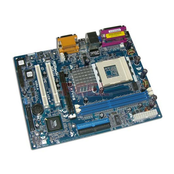
- Page 2 Motherboard L Motherboard L ayout PS2_USB_PWR1 jumper FID Jumpers (FID0, FID1, FID2, FID3, FID4) CPU fan connector (CPU_FAN1) CPU socket North Bridge controller 184-pin DDR DIMM slots (DDR 1- 2) ATX power connector (ATXPWR1) FSB select jumpers (FSB_SEL1)
- Page 3 ASRock I/O ASRock I/O Parallel port RJ-45 port Game port Microphone (Pink) Line In (Light Blue) Line Out (Lime) USB 2.0 ports VGA port PS/2 keyboard port (Purple) PS/2 mouse port (Green) 3 3 3 3 3 ASRock K7VM3 Motherboard...
- Page 4 This Quick Installation Guide contains introduction of the motherboard and step-by- step installation guide for new DIY system builders. More detailed information of the motherboard can be found in the user manual enclosed in the product CD-ROM. Because the motherboard specifications and the BIOS software might be updated, the content of this manual will be subject to change without notice.
- Page 5 USB 2.0: 4 default USB 2.0 ports and 1 extra set of header for two additional USB 2.0 ports upgrade (see CAUTION 3) ASRock I/O PS/2: 1 keyboard port / 1 mouse port; 1 RJ 45 port; 4 rear default USB 2.0 ports;...
- Page 6 Step 4. When the CPU is in place, press it firmly on the socket while you push down the socket lever to secure the CPU. The lever clicks on the side tab to indicate that it is locked.
- Page 7 Step 1. Unlock a DIMM slot by pressing the retaining clips outward. Step 2. Align a DIMM on the slot such that the notch on the DIMM matches the break on the slot. Step 3. Firmly insert the DIMM into the slot until the retaining clip snap back in place and the DIMM is properly seated.
- Page 8 Setting FSB_SEL1 (see p.2 item 8) Note: The setting of the CPU front side bus frequency of this motherboard is by means of the adjustment of jumper-setting. Please follow the figures above to set the CPU front side bus frequency.
- Page 9 (FID0, FID1, FID2, FID3, FID4) (see p.2 item 2) Note: The set of FID jumpers are designed to adjust the multiplier of CPU. For detailed information, please refer to page 14 of user Manual in the Support CD. Clear CMOS...
- Page 10 FDD connector (33-pin FLOPPY1) (see p.2 item 19) red marking Note: Match the red marking on the floppy ribbon cable with Pin1. Primary IDE connector (Blue) Secondary IDE connector (Black) (39-pin IDE1, see p.2 item 10) (39-pin IDE2, see p.2 item 9)
- Page 11 Front panel audio connector This is an interface for the front panel audio cable that allows (9-pin AUDIO1) convenient connection and (see p.2 item 26) control of audio devices. System panel connector This connector accommo- dates several system front (9-pin PANEL1) panel functions.
- Page 12 ME / 2000 / XP. The Support CD that came with the motherboard contains necessary drivers and useful utilities that will enhance motherboard features. To begin using the Support CD, insert the CD into your CD-ROM drive. It will display the Main Menu automatically if “AUTORUN” is enabled in your computer. If the Main Menu does not appear automatically, locate and double-click on the file ASSETUP.
- Page 13 ASRock K7VM3 Motherboard...
- Page 14 ® ® ASRock K7VM3 Motherboard...
- Page 15 ° ASRock K7VM3 Motherboard...
- Page 16 ASRock K7VM3 Motherboard...
- Page 17 ASRock K7VM3 Motherboard...
- Page 18 AUX1 ASRock K7VM3 Motherboard...
- Page 19 ® ® “PC-DIY Live Demo” ASRock “PC-DIY Live Demo” ® ® Microsoft Media Player ..\ MPEGAV \ AVSEQ01.DAT ASRock K7VM3 Motherboard...
- Page 20 1. Einführung 1. Einführung 1. Einführung Wir danken Ihnen für den Kauf des ASRock K7VM3 Motherboard, ein zuverlässiges Produkt, welches unter den ständigen, strengen Qualitätskontrollen von ASRock gefertigt wurde. Es bietet Ihnen exzellente Leistung und robustes Design, gemäß der Verpflichtung von ASRock zu Qualität und Halbarkeit.
- Page 21 PS/2 : Tastatur / Maus; RJ 45; 4 hintere USB 2.0-Ports; 1 VGA port; 1 paralleler port: Unterstützung für ECP/ EPP; Audioanschlüsse: Line Out / Line In / Mikrofon + Game port BIOS: AMI legal BIOS mit Unterstützung für “Plug and Play”;...
- Page 22 2. Um Schäden aufgrund von statischer Elektrizität zu vermeiden, das Motherboard NIEMALS auf einen Teppich o.ä.legen. Denken Sie außerem daran, immer ein geerdetes Armband zu tragen oder ein geerdetes Objekt aus Metall zu berühren, bevor Sie mit Systemkomponenten hantieren. 3. Halten Sie Komponenten immer an den Rändern und vermeiden Sie Berührungen mit den ICs.
- Page 23 Öffnen Sie einen DIMM-Slot, indem Sie die seitlichen Clips nach außen drücken. Schritt 2: Richten Sie das DIMM-Modul so über dem Slot aus, dass das Modul mit der Kerbe in den Slot passt. Schritt 3: Drücken Sie das DIMM-Modul in den Slot, bis die seitlichen Clips 2.3 Er...
- Page 24 +5VSB (Standby) zu setzen und (siehe S.2, Punkt 1) die PS/2 oder USB-Weckfunktionen zu aktivieren. Hinweis: Um +5VSB nutzen zu können, muss das Netzteil auf dieser Leitung 2A oder mehr leisten können. (siehe S.2, Punkt 25) (siehe S.2, Punkt 24) Hinweis: sind die Jumper JL1 und JR1 gesetzt funktionieren beide Audioanschlüsse, Front- und Rückseite.
- Page 25 Hinweis: Es gibt für Sie zwei Wege, die System-Parameter zurückzusetzen. Trennen Sie das Stromkabel vom Netz und überbrücken entweder die Lötpunkte an CLRCMOS1 für mehr als 3 Sekunden mit einem leitenden Gegenstand, z.B. einer Büroklammer, oder Sie nutzen eine Jumperkappe, um die Pins an CLRCMOS2 kurzzuschliessen.
- Page 26 USB 2.0-Anschlüsse ASRock I/O bietet bereits 4 USB 2.0-Ports auf der Rückseite (9-pin USB45) Wenn die 4 USB 2.0-Ports auf (siehe S.2, Punkt 20) der Rückseite nicht ausreichen, ist ein Slotblechadapter für zwei zusätzliche USB 2.0-Ports verfügbar. Anschluss für Dieser Anschluss unterstützt...
- Page 27 Anschluss für CPU-Lüfter Verbinden Sie das Lüfterkabel so, dass der Massepin der (3-pin CPU_FAN1) Anschlussbuchse mit dem (siehe S.2, Punkt 3) schwarzen Lüfterkabel übereinstimmt. Anschluss für ATX-Netzteil Dieser 20Pin-Anschluss ist zur Verwendung eines ATX 12V- (20-pin ATXPWR1) Netzteils gedacht. (siehe S.2, Punkt 7) Anschluss für seriellen port...
- Page 28 4. Software Suppor t CD information Dieses Motherboard unterstützt eine Reiche von Microsoft Windows Betriebssystemen: 98 SE / ME / 2000 / XP. Die Ihrem Motherboard beigefügte Support-CD enthält hilfreiche Software, Treiber und Hilfsprogramme, mit denen Sie die Funktionen Ihres Motherboards verbessern können Legen Sie die...
- Page 29 Des informations plus détaillées sur la carte mère sont fournies dans le manuel utilisateur sur le CD de support. Les spécifications de la carte mère et le BIOS ayant pu être mis à jour, le contenu de ce manuel est sujet à des changements sans notification.
- Page 30 AGP 1.5V, 4X (voir ATTENTION 2) Connecteur AMR: 1 connecteur, support de carte modem AMR USB 2.0: 4 ports USB 2.0 par défaut et un module pour 2 ports USB 2.0 supplémentaires (voir ATTENTION 3) ASRock I/O PS/2: clavier / souris;...
- Page 31 Etape 1. Déverrouillez le support en relevant le levier selon un angle de 90 Etape 2. Mettez en place le CPU au dessus du support de telle façon que l’angle portant une marque corresponde à la base du levier du support.
- Page 32 2.3 Connecteurs d’extension (connecteurs PCI, AMR et AGP) 2.3 Connecteurs d’extension (connecteurs PCI, AMR et AGP) Il y a 2 connecteurs PCI, 1 connecteur AMR, et 1 connecteur AGP sur la carte mère K7VM3. Connecteurs PCI: Les connecteurs PCI sont utilisés pour installer des cartes d’extension dotées d’une interface PCI 32 bits.
- Page 33 Note: Pour sélectionner +5VSB, il faut obligatoirement 2 Amp et un courant standby supérieur fourni par l’alimentation. (voir p.2 fig. 25) (voir p.2 fig. 24) Note: Si les cavaliers JL1 et JR1 sont reliés , les connecteurs audio du panneau avant et du panneau arrière peuvent fonctionner. ASRock K7VM3 Motherboard...
- Page 34 (voir p.2 fig. 2) Note: L’ensemble de cavaliers FID est conçu pour régler le coefficient multiplicateur du processeur. Pour obtenir des informations détaillées, veuillez vous référer à la page 14 du Manuel Utilisateur sur le CD de Support. Effacer la CMOS...
- Page 35 (FLOPPY1 br. 33) la marque rouge (voir p.2 fig. 19) Note: Faîtes correspondre la marque rouge du lecteur de disquette avec la broche 1. Connecteur IDE primaire(bleu) Connecteur IDE secondaire(noir) (IDE1 br. 39, voir p.2 fig. 10) (IDE2 br. 39, voir p.2 fig. 9)
- Page 36 à partir de sources (CD1 br. 4, AUX1 br. 4) stéréo comme un CD-ROM, DVD- (CD1: voir p.2 fig. 29) AUX1 ROM, un tuner TV ou une carte (AUX1: voir p.2 fig. 30) MPEG. Connecteur audio panneau C’est une interface pour un câble avant audio en façade qui permet le...
- Page 37 Cette carte mère supporte divers systèmes d’exploitation Microsoft Windows: 98 SE / ME / 2000 / XP. Le CD technique livré avec cette carte mère contient les pilotes et les utilitaires nécessaires pour améliorer les fonctions de la carte mère.
- Page 38 Grazie per aver scelto una scheda madre ASRock K7VM3, una scheda madre affidabile prodotta secondo i severi criteri di qualità ASRock. Le prestazioni eccellenti e il design robusto si conformano all’impegno di ASRock nella ricerca della qualità e della resistenza. Questa guida d’installazione rapida comprende la descrizione della scheda madre e una guida d’installazione passo a passo per i costruttori di nuovi...
- Page 39 (vedi ATTENZIONE 2) Slot AMR: 1 slot, supporta scheda modem AMR USB 2.0: 4 porte USB 2.0 integrate e un adattatore per 2 porte USB 2.0 (vedi ATTENZIONE 3) ASRock I/O PS/2: tastiera/ mouse; RJ 45; 4 porte USB 2.0 posteriori;...
- Page 40 Leggere le seguenti precauzioni prima di installare componenti delle schedemadri o di cambiare le impostazioni delle schedemadri. 1. Togliere il cavo dalla presa elettrica prima di toccare le componenti. In caso contrario la schedamadre, le periferiche, e/o i componenti possono subire gravi danni.
- Page 41 2.2 Installazione dei moduli di memoria (DIMM) 2.2 Installazione dei moduli di memoria (DIMM) 2.2 Installazione dei moduli di memoria (DIMM) La scheda madre K7VM3 è dotata di 2 slot DIMM DDR (Double Data Rate) a 184 pin. Installare una DIMM Installare una DIMM...
- Page 42 Jumper Settaggio del Jumper FSB_SEL1 (vedi p.2 item 8) Nota: Le immagini illustrano come si regola la frequenza del front side bus del processore. PS2_USB_PWR1 Cortocircuitare pin2, pin3 per settare a +5VSB (standby) e (vedi p.2 item 1) abilitare PS/2 o USB wake up events.
- Page 43 2 pin ponticelli Nota: Ci sono 2 modi per pulire e resettare i parametri di default del sistema. Per favore spegnere il computer e scollegare l’alimentatore. A questo punto è possible cortocircuitare i jumper posti su CLRCMOS1 utilizzando del materiale metallico, per esempio una graffetta, per più...
- Page 44 (CD1: vedi p.2 item 29) AUX1 ROM,TV tuner, o schede (AUx1: vedi p.2 item 30) MPEG. Connettore audio sul È un’interfaccia per il cavo del pannello frontale pannello audio. Che consente connessione facile e controllo (9-pin AUDIO1) dei dispositivi audio.
- Page 45 Connettore porta seriale Questa guida COM1 supporta un modulo porta seriale. (9-pin COM1) (vedi p.2 item 23) Connettore del LED di Collegare il cavo del LED di accensione accensione a 3 pin a questo connettore. (3-pin PWR_LED1) (vedi p.2 item. 16)
- Page 46 CD Questa scheda madre supporta vari sistemi operativi Microsoft Windows: 98 SE / ME / 2000 / XP. Il CD di supporto a corredo della scheda madre contiene i driver e utilità necessari a potenziare le caratteristiche della scheda.
- Page 47 La placa madre provee realización excelente con un diseño robusto conforme al compromiso de calidad y resistencia de ASRock. Esta guía contiene una introducción fácil de la placa madre e intrucción de paso a paso para instalación. Información detallada sobre la placa madre se puede encontrar en el manual del usuario presentado en el soporte CD.
- Page 48 PC. Por favor no use tarjeta AGP de 3.3 V sobre la ranuna AGP de K7VM3. Podría causar dano permanente.
- Page 49 Paso 1. Desbloquee el zócalo arrastrando la palanca hacia afuera y hacia arriba en un ángulo de 90 Paso 2. Coloque el CPU sobre el zócalo tal como la esquina marcada de CPU corresponde la esquina de zócalo cerca del terminal de la palanca, mientras tanto asegúrese que el CPU está...
- Page 50 Instalación de una DIMM Instalación de una DIMM Paso 1. Empuje los clips blancos de retención por el extremo de cada lado de la ranura de memoria. Paso 2. Encaje la muesca del DIMM hacia la cumbrera de la ranura.
- Page 51 3 para habilitar +5VSB (vea p.2, No. 1) (standby) para PS/2 o USB wake up events. Atención: Para elegir +5VSB, se necesita corriente mas que 2 Amp proveida por la fuente de electricidad. (vea p.2, No. 25) (vea p.2, No. 24) Atención: Si los puentes JL1 y JR1 son cortos, tanto el conector...
- Page 52 2 contactos Atención: Hay 2 maneras para limpiar y reconfigurar los parámetros del sistema a la configuración original de la fábrica. Por favor apague el computador y desconecte el cable de la fuente de electricidad; y después, Usted puede pongarse en cortocircuito los puntos de soldadura por más que...
- Page 53 USB 2.0 header ASRock I/O provee Usted 4 puertos USB 2.0 de la fábrica en (9-pin USB45) el panel posterior. Si los puertos (vea p.2, No. 20) USB 2.0 en el panel posterior no son suficientes, Usted puede usar el header de USB 2.0 para conectar a 2 puertos de USB 2.0 adicionales.
- Page 54 Conector de ventilador Conector para ventilador de CPU. de CPU (3-pin CPU_FAN1) (vea p.2, No. 3) Conector de ATX power Conector para ATX power supply. (20-pin ATXPWR1) (vea p.2, No. 7) Conector de Puerto Serial El COM1 header soporta un Módulo de Puerto Serial.
- Page 55 2000 / XP El CD de instalación que acompaña la placa-base trae todos los drivers y programas utilitarios para instalar y configurar la placa-base. Para iniciar la instalación, ponga el CD en el lector de CD y se desplegará el Menú Principal automáticamente si «AUTORUN» está habilitado en su computadora.
- Page 56 Gratos por comprar nossa placa–mãe K7VM3, um produto confiável feito com ASRock um estrito controle de qualidade consistente. Com um excelente desempenho, essa placa é dotada de um projeto robusto que atende a ASRock de compromisso com a qualidade e durabilidade.
- Page 57 PS/2: teclado / mouse; RJ-45; 4 portas default USB 2.0; 1 porta VGA; 1 porta paralela: com suporte ECP/EPP; Áudio Jack: saída / entrada de linha / microfone + porta de jogos BIOS: BIOS AMI; suporta dispositivos “Plug and Play”;...
- Page 58 Siga as precauções à seguir antes de instalar os componentes ou fazer qualquer ajuste na placa mãe. 1. Desligue o cabo de força da rede elétrica antes de tocar em qualquer componente. A falta desta precaução, a pessoa pode causar sérios danos à placa–mãe, periféricos e / ou componentes do sistema.
- Page 59 2.2 Instalação dos Módulos de Memória (DIMM) 2.2 Instalação dos Módulos de Memória (DIMM) 2.2 Instalação dos Módulos de Memória (DIMM) A placa mãe K7VM3 fornece 2 slots de DDR (Taxa Dupla de Dados) DIMM tem 184 pinos. Instalando uma DIMM...
- Page 60 (veja a folha 2, item 1) para PS/2 ou eventos de wake up na USB. Nota: Para escolher +5VSB, é preciso uma corrente de stand by de 2 A ou mais. (veja a folha 2, item 25) (veja a folha 2, item 24) Nota: Se os jumpers JL1 e JR1 estiverem conectados , tanto os conectores do painel frontal quanto do traseiro funcionarão.
- Page 61 3 segundos para limpar a CMOS usando algum material metálico, por exemplo: um grampo de papel ou ponha em curto–circuito os pins de CLRCMOS2 por mais de 3 segundos para limpar o CMOS usando um jumper cap.
- Page 62 (FLOPPY 1, 33 pinos) (veja a folha 2, item 19) Marca Vermelha Nota: alinhe a marca vermelha no cabo da cinta do disquete com o Pin1. Conector primário (azul) Conector secundário de IDE (preto) (IDE1 de 39 pinos, veja a folha 2, item 10)
- Page 63 áudio em estéreo de fontes AUX1 de 4 pinos) AUX1 de áudio como CD-ROM, (CD1: veja a floha 2, item 29) DVD-ROM, placa sintonizadora (AUX1: veja a floha 2, item 30) de TV ou placa MPEG. Conector Áudio do painel Esta é...
- Page 64 BIOS; caso contrário o POST continua com suas rotinas de teste. Caso você queira entrar nas configurações da BIOS após o POST, reinicie o sistema pressionando <Ctrl> + <Alt> +<Del>, ou pressionando a tecla de reset no gabinete.
Need help?
Do you have a question about the K7VM3 and is the answer not in the manual?
Questions and answers