
Subscribe to Our Youtube Channel
Related Manuals for RefPlus FLAT SLAB FND Series


Summary of Contents for RefPlus FLAT SLAB FND Series
- Page 1 INSTALLATION, OPERATION AND MAINTENANCE MANUAL AIR-COOLED FLUID COOLERS FLAT SLAB FND-FLD-FMD-FCD-FBD-FVD SERIES...
-
Page 3: Table Of Contents
TABLE OF CONTENTS 1. INTRODUCTION ......................... 2. SAFETY CONSIDERATIONS ...................... 3. PRODUCT DESCRIPTION ......................4. CU NOMENCLATURE ......................... 5. HANDLING AND RIGGING ......................6. INSTALLATION ..........................6.1 STORAGE ................................8 6.2 COMPLETE PRE-INSTALLATION INSPECTION ....................8 6.3 START-UP REPORT FORM ............................ 8 6.4 INSTALLATION LOCATION ............................ -
Page 4: Introduction
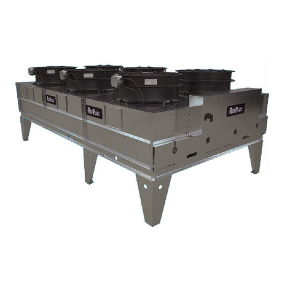
3. PRODUCT DESCRIPTION Congratulations on purchasing an air-cooled, flat slab RefPlus' flat slab fluid coolers are closed loop industrial dry Fluid Cooler from RefPlus. Your unit has been thoroughly type air-cooled fluid coolers available in a array of sizes for inspected and leak tested before shipment to ensure peak process cooling applications. -
Page 5: Cu Nomenclature
4. NOMENCLATURE 2 B L 8 0 3 2 AIR FLOW SPEED OPTION H = Horizontal air flow L = Low speed S = Horizontal air flow and low speed FINS PER INCH B = 8 FPI D = 10 FPI F = 12 FPI G = 14 FPI CIRCUIT QUANTITY... -
Page 6: Handling And Rigging
HANDLING AND RIGGING 5. HANDLING AND RIGGING The center of gravity must be identified before lifting the unit. The crane, hooks, chains, straps, and load spreader Good handling and rigging practices must be followed bars must be determined according to the unit weight. to protect units from damage. - Page 7 HANDLING AND RIGGING Two methods are recommended for lifting the unit in Lifting method 2: position: 1. Gently lower the unit on a flat surface. Lifting method 1: 2. Install hangers on opposite side. 1. Install all the legs on the same side as hangers. 3.
-
Page 8: Installation
This form is also available at the end Fluid coolers, piping, coil and disconnect switch should of this manual or online at refplus.com, under the Service tab. not be accessible to unauthorized persons. To shield the equipment from tampering and vandalism and to protect 6.4 INSTALLATION LOCATION... -
Page 9: Installation Precautions
INSTALLATION 40” (1000mm) 48” (1220mm) 24” 48” (610mm) (1220mm) 48” 96” (1220mm) (2440mm) SINGLE-ROW UNITS DOUBLE-ROW UNITS Figure 4 Minimum required space around unit 6.5 INSTALLATION PRECAUTIONS Welded or sweat joints should be used. Teflon tape should be used on threaded pipe joints. Dry nitrogen must be swept Important things to keep in mind during installation: through the lines while joints are brazed to avoid oxidation •... -
Page 10: Installing The Temperature Sensor
INSTALLATION Proper piping vibration isolation must be provided. Sensor must be positioned, secured and isolated as shown Generally, horizontal-piping runs should grade slightly in Figure 7. downwards, in the direction of the flow. IMPORTANT: Sensor must be properly isolated to avoid a miss-reading. - Page 11 INSTALLATION SYSTEM WITH NO 3-WAY VALVE OR WITH 3-WAY VALVE CONTROLLED BY EXTERNAL CONTROLLER SYSTEM WITH 3-WAY VALVE CONTROLLED BY GUARDIAN+ RC-F Figure 8 Sensor locations for single-coil unit configurations - with or without 3-way valve DUAL GUARDIAN+ RC-F CONTROLLER SYSTEM (SPLIT) WITH NO 3-WAY VALVE OR WITH 3-WAY VALVE CONTROLLED BY...
-
Page 12: Leak Testing
INSTALLATION 6.8 LEAK TESTING MODEL VOLUME Leak testing and evacuation must be done in accordance "E" PATTERN (US GAL) with local and national codes. Once all fluid connections 1 FAN WIDE are made, leak test all joints before charging the system. F*D-112*-*-E 6.9 FLUID CHARGING F*D-113*-*-E... -
Page 13: Unit Wiring
INSTALLATION PIPE DIAMETER VOLUME PER 100 FEET MODEL MODEL VOLUME VOLUME (INCHES) OF PIPE (GALLONS) "F" PATTERN "F" PATTERN (US GAL) (US GAL) 1 FAN WIDE 2 FAN WIDE 5/8” F*D-112*-*-F 3/4” F*D-113*-*-F 7/8” F*D-114*-*-F 1-1/8” F*D-122*-*-F F*D-222*-*-F 11.2 1-5/8” F*D-123*-*-F F*D-223*-*-F 16.8... -
Page 14: Fan Motors
Test procedure when unit is controlled by electro-mechanical and higher discharge pressure along with reduced unit System C450 controls: capacity. Please consult a RefPlus representative if you Once the control module has been setup, meaning that the suspect this situation. -
Page 15: When Unit Is Running
The manual is supplied with your unit but the • Always aim the jet vertically, as shown in Figure 126. most recent version can be downloaded at https://refplus. • If fins are greasy or oily, it helps to add a mild, com/wp-content/uploads/2021/05/IOM-Guardian-RC-F- environmentally friendly cleaning agent to the water. - Page 16 MAINTENANCE SYSTEM MAINTENANCE: The system should be checked periodically by a qualified air conditioning service company. If using other than glycol solutions, the coils should be flushed annually to keep scale deposits down for maximum heat transfer efficiency. The water should be tested by a local testing firm. This also applies should an automatic water treatment be used.
-
Page 17: Troubleshooting
2. Bypass not installed. Poor system diagrams. performance 3. Replace impeller or seals as necessary. 3. Worn impeller or seals on pump. 4. Replace bearings. mp motor bearings. 4. Worn pu 12. REPLACEMENT PARTS Download the parts manual at http://refplus.com/en/parts-services/... -
Page 18: Start-Up Form
START-UP FORM START-UP REPORT FORM IMPORTANT: This startup report form must be filled out, signed and sent to RefPlus for the warranty to be honoured. 1. GENERAL INFORMATION JOB LOCATION: ____________________________________________________________________________________________________________________________________ REFPLUS RJ No: CONTRACTOR NAME: FLUID COOLER MODEL No.: FLUID COOLER SERIAL No.:... - Page 19 START-UP FORM START-UP REPORT FORM - OPTIONAL ADIABATIC SYSTEM IMPORTANT: This startup report form must be filled out, signed and sent to RefPlus for the warranty to be honoured. PRE-START-UP (Check each item when completed) CHECK WATER SUPPLY CHECK AIR VENT (PROPER CONNECTION) ...
-
Page 20: Unit Dimensions
nit dimensions 39 1/2 [1003] 31 1/2 [203] [800] [711] [127] [1117] [990] [431] 9/16ø [14] - 4 MOUNTING HOLES [838] UNIT DIMENSIONS (INCHES [MM]) [203] [1118] [991] [432] 9/16ø [14] - MOUNTING HOLES UNIT DIMENSIONS (INCHES [MM]) ARRANGEMENT 43 [1092] 49 1/2 [1257] 41 1/2 [1054] 38 [965]... - Page 21 nit dimensions FLD-FND-FVD-FBD [203] * MODELS W/ ZIEHL-ABEGG FANS ONLY 59 7/8* 52** [1522] [1321] [1194] [559] 9/16ø [14] - MOUNTING HOLES ** OVERALL HEIGHT FOR MODELS W/ STANDARD EFFICIENCY FANS UNIT DIMENSIONS (INCHES [MM]) ARRANGEMENT 60 [1524] 66 1/2 [1989] 58 1/2 [1485] 48 [1219] 117 [2972]...
-
Page 22: Typical Wiring Diagrams
STANDARD-EFFICIENCY FANS W/OUT CONTROLS iring iagrams 208/3/60 208V N.F.D. 15A CC 250VA 15A CC 15A CC 15A CC #C : Main Contactor M# : Fan Motor MF# : Motor Fuses 15A CC NFD : Non Fused Disconnect 15A CC... - Page 23 STANDARD-EFFICIENCY FANS W/ AQUASTAT CONTROLS STANDARD-EFFICIENCY FANS W/ AQUASTAT CONTROLS iring iring iagrams iagrams 600/3/60 600V 600V N.F.D. 6A CC 250VA 75VA CLASS SENSOR 1 6A CC C450CCN 6A CC C450SCN 6A CC C450SCN #C : Main Contactor CCN : Control Module M# : Fan Motor MF# : Motor Fuses 6A CC...
- Page 24 HIGH-EFFICIENCY FANS W/OUT CONTROLS iring iagrams 600/3/60 DETAIL "A" TYP. USE COPPER SUPPLY WIRES L3 BLACK L2 RED L1 BLUE N.F.D. 600V 10A CC 250VA 120V 10A CC 10A CC TB10 10A CC TB11 TB12 RELAY LINE USED FOR THE HIGH/LOW FUNCTIONS OF MOTORS.
- Page 25 HIGH-EFFICIENCY FANS W/ AQUASTAT CONTROLS iring iagrams USE COPPER SUPPLY WIRES 600/3/60 DETAIL "A" TYP. BLACK BLUE N.F.D. 600V 600V 6A CC 250VA 75VA CLASS N.O. SENSOR 1 6A CC N.O. C450CCN N.O. 6A CC N.O. C450SCN TB10 N.O. 6A CC N.O.
- Page 26 HIGH-EFFICIENCY ECM FANS W/ AQUASTAT CONTROLS iring iagrams USE COPPER SUPPLY WIRES 600/3/60 DETAIL "A" 5700VA BLACK BLUE ATF1 N.F.D. 600V 600V 8A CC 10A CC 150VA 75VA CLASS DETAIL "B" N.O. 10A CC SENSOR 1 N.O. C450CCN 10A CC C450SBN 10A CC ECM WIRING...
- Page 27 HIGH-EFFICIENCY FANS W/OUT CONTROLS - ADIABATIC iring iagrams USE COPPER SUPPLY WIRES DETAIL "A" TYP. 600/3/60 BLACK BLUE N.F.D. 600V 10A CC 250VA 10A CC 10A CC INTERLOCK TB10 10A CC (TO BE INST'L UNDER ELECTRICAL BOX) TB11 TB12 (TO BE INST'L ON LIQUID HEADER) RELAY LINE USED FOR THE HIGH/LOW FUNCTIONS OF MOTORS.
-
Page 28: Typical Field Piping Diagram
TYPICAL FIELD PIPING DIAGRAM iPing iagrams... -
Page 29: General Warranty
GENERAL WARRANTY REFPLUS (SELLER) WARRANTS THAT THE EQUIPMENT MANUFACTURED BY THE SELLER, INCLUDING SERVICE PARTS, AND SOLD UNDER THIS CONTRACT SHALL BE FREE FROM DEFECTS IN MATERIAL AND WORKMANSHIP FOR A PERIOD OF TWELVE (12) MONTHS FROM THE DATE OF EQUIPMENT START-UP OR EIGHTEEN (18) MONTHS FROM THE DATE OF SHIPMENT, WHICHEVER OCCURS FIRST. - Page 30 LINECARD CERTIFIED ISO-9001 IOM_FLAT FLUID COOLER_EN-R1 RefPlus Inc. reserves the right to make any changes in the design or specifications of any product at any time without notice. USA & CANADA 1-888-816-2665 / refplus.com © Copyright 2024 by RefPlus Inc.
Need help?
Do you have a question about the FLAT SLAB FND Series and is the answer not in the manual?
Questions and answers