
Related Manuals for RefPlus Opti-Mist Plus


Summary of Contents for RefPlus Opti-Mist Plus
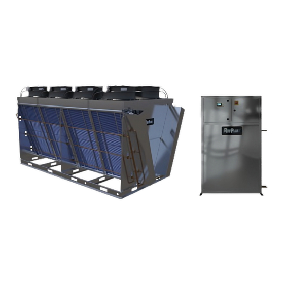
- Page 1 INSTALLATION, OPERATION AND MAINTENANCE MANUAL ADIABATIC PRE-COOLING SYSTEM Opti-Mist Plus...
-
Page 2: Table Of Contents
TABLE OF CONTENTS ADIABATIC SYSTEM MAIN COMPONENTS .................. PUMPING STATION & WATER TREATMENT MAIN COMPONENTS ..........1. INTRODUCTION .......................... 2. SAFETY CONSIDERATIONS ...................... 3. PRODUCT DESCRIPTION ......................4. INSTALLATION ..........................4.1 LOCATING AND SECURING THE PUMPING STATION ..................5 4.2 PIPING ..................................6 4.3 WIRING ................................... -
Page 3: Adiabatic System Main Components
diAbAtic yStem omponentS ATOMIZING NOZZLES PIPING NETWORK PUMPING AND WATER TREATMENT STATION... -
Page 4: Pumping Station & Water Treatment Main Components
& W umping tAtion Ater reAtment omponentS GUARDIAN+ RC-A CONTROLLER WATER PRESSURE REGULATING VALVE WATER INLET (City water or tank) PRESSURE DIFFERENTIAL SWITCH UV LIGHT WATER PARTICLE FILTER DEMINERALIZER (ANTI-SCALING) WATER OUTLET (To heat rejection unit) DRAIN DRAIN (UV light flush) PULSING VALVE PUMP... -
Page 5: Introduction
Congratulations on purchasing an Opti-Mist+ Adiabatic ® A unit-mounted interlock authorizes the system to run. A Pre-Cooling System from RefPlus . Your system has been ® fluid temperature and an outside temperature sensors vary thoroughly inspected and leak tested before shipment to the required USGPM to cool the air before entering the heat ensure peak performance. -
Page 6: Piping
Figure 2 Piping connections installation and sent back to RefPlus. This is to insure proper follow-up from the manufacturer and to activate the warranty. This form is also available at the end of this All piping should have a minimum slope of 1/4"/12"... -
Page 7: Water Pressure Adjustment
WATER PRESSURE ADJUSTMENT FLAT SLAB MODELS “V” MODELS “W” MODELS Figure 4 Proper nozzle orientation 6. WATER PRESSURE ADJUSTMENT When pump outlet valve (3) is closed, pressure should not be above 85 psi. If you are not able to meet this outlet pressure Inlet water pressure: and if it is too high, lower the inlet water pressure (1) as close Water pressure is adjusted through a regulating valve on the... -
Page 8: Maintenance
Refer to the Controller's Programming Manual to complete the RefPlus recommends a monthly check of the spray nozzles configuration and adjustments, such as the temperature and the water distribution piping for damage and uniform settings, system selection, etc. -
Page 9: Troubleshooting
TROUBLESHOOTING 9. TROUBLESHOOTING PROBLEM POSSIBLE CAUSES POSSIBLE CORRECTIVE STEPS Check if Status on Main Status screen is ON. If not, switch the system ON and check for alarms and continue troubleshooting. Check Offsets. They should be at zero during normal operation or can be used to simulate FT and OT to create a Cooling demand. - Page 10 TROUBLESHOOTING PROBLEM POSSIBLE CAUSES POSSIBLE CORRECTIVE STEPS Reduce amount of water delivered to the nozzles. Refer to the Operation Principle/Sequence of Operation section of the adiabatic controller programming manual to understand your configuration and adjust the amount of water by following Great amount of water is dropping Too much water to the instructions on page 17 to page 19.
- Page 11 TROUBLESHOOTING PROBLEM POSSIBLE CAUSES POSSIBLE CORRECTIVE STEPS If using city water, make sure pump inlet pressure is at least 40 psi. Make sure there is no restriction and inlet pipe dimension is respected according to the information supplied previously in this manual. Low-pressure switch may be damaged. Check low-pressure switch.
-
Page 12: Replacement Parts
REPLACEMENT PARTS LIST ITEM PART # PART DESCRIPTION RPL-0080 DEMINERALIZER (ANTI-SCALE) COMPLETE SYSTEM - WATTS ONEFLOW RPL-0084 DEMINERALIZER (ANTI-SCALE) BIG BLUE O-RING - WATTS ONEFLOW RPL-0083 DEMINERALIZER (ANTI-SCALE) CARTRIDGE - WATTS ONEFLOW RPL-0085 DEMINERALIZER (ANTI-SCALE) COMPLETE SYSTEM - TAC-LER RPL-0086 DEMINERALIZER (ANTI-SCALE) CARTRIDGE - TAC-LER RPL-0051 UV LIGHT COMPLETE SYSTEM... -
Page 13: Startup Report Form
START-UP REPORT FORM ADIABATIC SYSTEM STARTUP REPORT FORM IMPORTANT: This startup report form must be filled out, signed and sent to RefPlus for the warranty to be honoured. PRE-START-UP (Check each item when completed, as recommended in this manual. ... -
Page 14: Unit Dimensions
nit dimenSionS 20 1/4” 36 1/4” WATER INLET (CITY WATER OR TANK) 7/8” OD WATER OUTLET (TO COOLING UNIT) 5/8” OD (4 GPM) 7/8” OD (8 GPM) COOLING UNIT DRAIN OUTLET 5/8” OD APPROXIMATE WEIGHT: 350 LBS / 160 Kg UV LAMP DRAIN OUTLET 5/8”... -
Page 15: Wiring Diagrams
TYPICAL WIRING DIAGRAM FOR 120V/1PH/60Hz iring iAgrAmS IMPORTANT: THIS PUMP SYSTEM IS USED ON OPEN SPRAY APPLICATION AND MUST BE PLUGGED INTO ELECTRICAL SERVICE WHICH IS PROTECTED BY A GROUND FAULT CIRCUIT INTERRUPTER. DISCONNECT SWITCH 120/1/60 F 25A 150 VA 50 VA F 10A Tx/Rx... - Page 16 TYPICAL WIRING DIAGRAM FOR 230V/1PH/60Hz iring iAgrAmS IMPORTANT: THIS PUMP SYSTEM IS USED ON OPEN SPRAY APPLICATION AND MUST BE PLUGGED INTO ELECTRICAL SERVICE WHICH IS PROTECTED BY A GROUND FAULT CIRCUIT INTERRUPTER. DISCONNECT SWITCH 230/1/60 F 15A 150 VA 50 VA F 10A Tx/Rx...
- Page 17 TYPICAL WIRING DIAGRAM FOR 208V/3PH/60Hz iring iAgrAmS IMPORTANT: THIS PUMP SYSTEM IS USED ON OPEN SPRAY APPLICATION AND MUST BE PLUGGED INTO ELECTRICAL SERVICE WHICH IS PROTECTED BY A GROUND FAULT CIRCUIT INTERRUPTER. DISCONNECT SWITCH 208/3/60 F 15A 150 VA 100 VA 50 VA F 10A...
-
Page 18: Piping Diagram
TYPICAL PIPING DIAGRAM iping iAgrAm WATER DRAIN SUPPLY TO UNIT WATER INLET (CITY WATER) TO DRAIN TO DRAIN PUMPING STATION AND TREATMENT CABINET WITH CITY WATER CONNECTION MANUAL VALVE SOLENOID VALVE WATER FILTER MANUAL BY-PASS DEMINARILIZER PRESSURE REDUCING VALVE UV LAMP CHECK VALVE PRESSURE REGULATING VALVE PRESSURE GAUGE ACCESS 1/4 FPT (GAUGE BY OTHER) -
Page 19: Warranty
WARRANTY RefPlus warrants the labeled (serial no.) new Refplus equipment and all parts thereof, to be free from defects in workmanship ® and material at the time of purchase. Apply to original purchaser only (not transferable). Under this warranty, RefPlus shall be limited to repairing or exchanging any parts, without charge FOB factory or nearest ®... - Page 20 IOM-ADIABATIC SYSTEM_EN-R0 CERTIFIED ISO-9001 RefPlus Inc. reserves the right to make any changes in the design or specifications of any product at any time without notice. © Copyright 2021 by RefPlus Inc. USA & CANADA 1-888-816-2665 / refplus.com 10/21 2777 Grande-Allée,Saint-Hubert, Québec,Canada,J4T 2R4 T 450 641-2665 F 450 641-4554...
Need help?
Do you have a question about the Opti-Mist Plus and is the answer not in the manual?
Questions and answers