RefPlus LS Series Installation, Operation And Maintenance Manual
Commercial walk-in evaporators
Hide thumbs
Also See for LS Series:

Subscribe to Our Youtube Channel
Related Manuals for RefPlus LS Series


Summary of Contents for RefPlus LS Series
- Page 1 INSTALLATION, OPERATION AND MAINTENANCE MANUAL COMMERCIAL WALK-IN EVAPORATORS LS-LV-LA-LP SERIES AWEF REGISTERED...
-
Page 3: Table Of Contents
TABLE OF CONTENTS 1. SAFETY CONSIDERATIONS ..........................4 2. INTRODUCTION ..............................4 3. PRODUCT DESCRIPTION ..........................4 4. NOMENCLATURE ..............................5 5. HANDLING AND RIGGING ..........................6 5.1 STANDARD UNIT WEIGHTS ..........................7 5.2 R-448A OPERATING CHARGES ..........................7 6. INSTALLATION ................................ -
Page 4: Safety Considerations
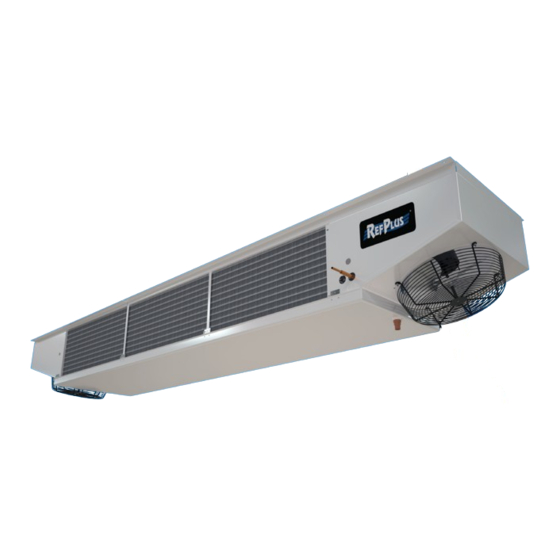
LS series are single-coil construction for an air distribution towards the centre of the cooler and freezer. The fans draw air from the evaporator coil and discharge it through the fan guards at the front of the unit. -
Page 5: Nomenclature
4. NOMENCLATURE 2 3 5 OPTIONS A = AWEF compliant L = Low speed MODEL GENERATION 0-6 = Conventional refrigerant generation 7-9 = CO generation MODEL NUMBER / NOMINAL CAPACITY @ 10°FTD 2350 = 235 000 BTU/H 043 = 4300 BTU/H VOLTAGE DEFROST TYPE A = Air defrost... -
Page 6: Handling And Rigging
HANDLING AND RIGGING 5. HANDLING AND RIGGING Your unit is shipped crated on a pallet. This prevents any damage to the drain pan underneath. To fasten the unit to the Good handling and rigging practices must be followed to ceiling, it is recommended to leave it on the pallet in order to protect units from damage. -
Page 7: Standard Unit Weights
STANDARD UNIT WEIGHTS / OPERATING CHARGES 5.1 STANDARD UNIT WEIGHTS (LB.) 5.2 R-448A OPERATING CHARGES (LB.) SHIPPING SHIPPING SHIPPING OPERATING OPERATING OPERATING MODEL MODEL MODEL MODEL MODEL MODEL WEIGHT WEIGHT WEIGHT CHARGE CHARGE CHARGE LSA-0451 LSE-0431 LSR/LST-0431 LSA-0451 0.85 LSE-0431 0.71 LSR/LST-0431 0.85... -
Page 8: Installation
• LV models: 2 ft minimum - 12 ft maximum • LA-LP models: 3 ft minimum - 20 ft maximum All RefPlus evaporators are pressurized with dry air. A lack of pressure does not indicate a leak. Check the coil NOTE: Units with electric defrost require a minimum clearance for possible leaks before installing or returning the unit. - Page 9 INSTALLATION 1/2 H min. 1 H recommended 3’ min. 3’ min. (W for units w/electric defrost) Flow 2’ min. 3’ min. LA-LP 12’ max. 20’ max. 3’ min. 3’ min. LV-LA-LP (W for units w/electric defrost) Figure 2 Single-evaporator clearance (H=Height of unit - W=Width of unit) 1/2 H min.
-
Page 10: Connecting Drain Line
INSTALLATION 6.4 CONNECTING DRAIN LINE Drain traps on low temperature units must be outside of refrigerated enclosures. Properly protected from freezing, A drain line union is recommended for ease of installation copper or steel pipes should be used. Food approved plastic and future servicing and should be located in close proximity can also be used for medium temperature coolers above 35°F to the drain pan. -
Page 11: Connecting The Expansion Valve
INSTALLATION 6.6 CONNECTING THE EXPANSION VALVE All units are supplied with a sweat expansion valve connection. Expansion valves are field supplied or may have been installed at the factory (optional). All units require the use of an externally equalized expansion valve and are provided with a 1/4"... -
Page 12: Suction Line Construction
INSTALLATION 6.8 SUCTION LINE CONSTRUCTION RECOMMENDED VELOCITY FOR GOOD OIL RETURN OF POE WITH HFC - FPM (M/S) Minimum Minimum Design Maximum Horizontal Vertical Condensate ≤ 100 (0.5) 150 (0.8) Liquid ≤ 300 (1.5) 300 (1.5) Suction 500 (2.5) 900 (4.6) 1000 (5.1) - 3000 (15.2) 4000 (20.3) Discharge... - Page 13 INSTALLATION SUCTION LINE SUCTION LINE TO COMPRESSOR TO COMPRESSOR EVAP. EVAP. RED TEE RED TEE STR. STR. ELLS ELLS U-BEND OR 2 ELLS Figure 8 Double suction riser DOUBLE RISER WHEN DOUBLE RISER NECESSARY WHEN NECESSARY MULTIPLE EVAPORATORS MULTIPLE EVAPORATORS MULTIPLE EVAPORATORS ON MULTIPLE EVAPORATORS ON STACKED ON SAME LEVEL:...
-
Page 14: External Equalizer Location
INSTALLATION 6.9 EXTERNAL EQUALIZER LOCATION Wiring diagrams are shown at the end of this manual for reference only. Always refer to the wiring diagram supplied The purpose of the external equalizer is to sense the pressure with your specific unit. in the suction line at the bulb location and transmit it to the When field wiring the unit, consider the following: TEV diaphragm. -
Page 15: Start Up
START-UP 7. START-UP 7.4 FAN DELAY DRAIN PAN CONTROL The fan delay drain pan control senses the general coil CCAUTION: Before starting unit, be sure wire temperature. fan guards are secured in place over each fan. • With temperature rise, the fan delay thermostat de- energizes the fan and energizes the electric pan heaters. -
Page 16: Defrost System
NOTE: A minimum of 3 evaporators is required for an efficient operation. Special engineering is required for a 1 or 2 evaporator configuration. Please contact RefPlus' Sales-Engineering department for proper selection. NOTE: A field-installed pressure regulating valve may be required on low temperature systems to control compressor crankcase pressure. -
Page 17: Service
SERVICE 9. SERVICE CAUTION: Before starting unit, be sure wire fan guards are securely fastened over each fan. 9.1 INITIAL INSPECTION 9.3 CLEANING After the system has been charged and has operated for at WARNING! Before carrying out any cleaning or least two hours at normal operating conditions without any maintenance of the unit, always check to make indication of malfunction, it should be allowed to operate... -
Page 18: Troubleshooting Chart
Uneven coil 3. Defrost termination set too low. 3. Adjust defrost termination setting higher. frosting 4. Incorrect or missing distributor nozzle. 4. Add or replace nozzle with appropriate sized orifice for conditions. 11. REPLACEMENT PARTS Download the parts manual at refplus.com... -
Page 19: Evaporator Start-Up Report Form
EVAPORATOR START-UP REPORT FORM 12. EVAPORATOR START-UP REPORT FORM IMPORTANT: This startup report form must be filled out, signed and sent to RefPlus for the warranty to be honoured. 1. GENERAL INFORMATION JOB LOCATION: __________________________________________________________________________________________________________________________ REFPLUS RJ No: CONTRACTOR NAME: UNIT COOLER MODEL No.:... - Page 20 ADJUSTABLE FAN DELAY SETTING 5. FIELD INSTALLED EXPANSION VALVE MANUFACTURER MODEL DATE: TECHNICIAN: (YY/MM/DD) SIGNATURE: FILL OUT FORM MANUALLY, TAKE A PHOTO SCAN THE QR CODE LOCATED IN THE AND SEND TO: CONTROL PANEL OF YOUR UNIT TO ACCESS service@refplus.com THE ONLINE FORM...
-
Page 21: Wiring Diagrams
WIRING DIAGRAMS 13. WIRING DIAGRAMS 13.1 TYPICAL WIRING DIAGRAMS FOR LSA-LVA-LAA-LPA MODELS - AIR DEFROST ECM TWIN-SPEED MOTORS - 120/1/60 (12" FANS) WIRING DIAGRAMS ARE FOR REFERENCE ONLY. REFER TO DIAGRAM SUPPLIED WITH YOUR UNIT. USE COPPER CONDUCTOR ONLY SINGLE SPEED AS BUILT BLACK TWO SPEED 120/1/60... - Page 22 WIRING DIAGRAMS 13.1 TYPICAL WIRING DIAGRAMS FOR LSA-LVA-LAA-LPA MODELS - AIR DEFROST ECM TWIN-SPEED MOTORS - 240/1/60 (12" FANS) WIRING DIAGRAMS ARE FOR REFERENCE ONLY. REFER TO DIAGRAM SUPPLIED WITH YOUR UNIT. SINGLE SPEED AS BUILT BLACK TWO SPEED 240/1/60 INTERLOCK WHITE 1R : RELAY FOR TWO SPEED OPERATION...
- Page 23 WIRING DIAGRAMS 13.1 TYPICAL WIRING DIAGRAMS FOR LSA-LVA-LAA-LPA MODELS - AIR DEFROST ECM 0-10V MOTORS - 240/1/60 (12" FANS) - OPTIONAL WIRING DIAGRAMS ARE FOR REFERENCE ONLY. REFER TO DIAGRAM SUPPLIED WITH YOUR UNIT. 240/1/60 USE COPPER SUPPLY WIRES BLACK 24 VAC BLUE GREEN...
-
Page 24: Lva-Laa-Lpa Models - Air Defrost
WIRING DIAGRAMS 13.2 TYPICAL WIRING DIAGRAMS FOR LVA-LAA-LPA MODELS - AIR DEFROST ECM TWIN-SPEED MOTORS - 120/1/60 (10" FANS) WIRING DIAGRAMS ARE FOR REFERENCE ONLY. REFER TO DIAGRAM SUPPLIED WITH YOUR UNIT. SINGLE SPEED AS BUILT BROWN TWO SPEED 120/1/60 INTERLOCK BLUE BLACK... - Page 25 WIRING DIAGRAMS 13.2 TYPICAL WIRING DIAGRAMS FOR LVA-LAA-LPA MODELS - AIR DEFROST ECM TWIN-SPEED MOTORS - 240/1/60 (10" FANS) WIRING DIAGRAMS ARE FOR REFERENCE ONLY. REFER TO DIAGRAM SUPPLIED WITH YOUR UNIT. SINGLE SPEED AS BUILT BROWN TWO-SPEED 240/1/60 INTERLOCK BLUE BLACK 1R : RELAY FOR TWO-SPEED OPERATION...
- Page 26 WIRING DIAGRAMS 13.2 TYPICAL WIRING DIAGRAMS FOR LVA-LAA-LPA MODELS - AIR DEFROST ECM 0-10V MOTORS - 240/1/60 (10" FANS) - OPTIONAL WIRING DIAGRAMS ARE FOR REFERENCE ONLY. REFER TO DIAGRAM SUPPLIED WITH YOUR UNIT. USE COPPER SUPPLY WIRES 240/1/60 BLACK WHITE GREY GREEN...
-
Page 27: Lse-Lve-Lae-Lpe Models - Electric Defrost
WIRING DIAGRAMS 13.3 TYPICAL WIRING DIAGRAMS FOR LSE-LVE-LAE-LPE MODELS - ELECTRIC DEFROST WIRING DIAGRAMS ARE FOR REFERENCE ONLY. ECM HIGH-SPEED MOTORS - 120/1/60 (12” FANS) REFER TO DIAGRAM SUPPLIED WITH YOUR UNIT. USE COPPER CONDUCTOR ONLY 120/1/60 BLACK WHITE BROWN BLACK DTFD ECM HIGH-SPEED MOTORS - 240/1/60 (12”... - Page 28 WIRING DIAGRAMS 13.3 TYPICAL WIRING DIAGRAMS FOR LSE-LVE-LAE-LPE MODELS - ELECTRIC DEFROST ECM 0-10V MOTORS - 240/1/60 (12" FANS) - OPTIONAL WIRING DIAGRAMS ARE FOR REFERENCE ONLY. REFER TO DIAGRAM SUPPLIED WITH YOUR UNIT. 240/1/60 USE COPPER CONDUCTOR ONLY BLACK WHITE BROWN BLACK...
-
Page 29: Lve-Lae-Lpe Models - Electric Defrost
WIRING DIAGRAMS 13.4 TYPICAL WIRING DIAGRAMS FOR LVE-LAE-LPE MODELS - ELECTRIC DEFROST ECM HIGH-SPEED MOTORS - 120/1/60 (10” FANS) WIRING DIAGRAMS ARE FOR REFERENCE ONLY. REFER TO DIAGRAM SUPPLIED WITH YOUR UNIT. 120/1/60 USE COPPER CONDUCTOR ONLY BROWN BLUE BLACK BROWN BLACK DTFD... - Page 30 WIRING DIAGRAMS 13.4 TYPICAL WIRING DIAGRAMS FOR LVE-LAE-LPE MODELS - ELECTRIC DEFROST ECM 0-10V MOTORS - 240/1/60 (10” FANS) - OPTIONAL WIRING DIAGRAMS ARE FOR REFERENCE ONLY. REFER TO DIAGRAM SUPPLIED WITH YOUR UNIT. 240/1/60 USE COPPER SUPPLY WIRES BLACK WHITE BROWN BLACK...
-
Page 31: Lsr-Lst Models - Hot-Gas Defrost
WIRING DIAGRAMS 13.5 TYPICAL WIRING DIAGRAMS FOR LSR-LST MODELS - HOT-GAS DEFROST ECM HIGH-SPEED MOTORS - 120/1/60 & 240/1/60 (12” FANS) WIRING DIAGRAMS ARE FOR REFERENCE ONLY. 120/1/60 REFER TO DIAGRAM SUPPLIED WITH YOUR UNIT. USE COPPER CONDUCTOR ONLY USE COPPER CONDUCTOR ONLY BLACK BLACK 120/1/60... -
Page 32: La-Lp Models - Hot-Gas Defrost
WIRING DIAGRAMS 13.6 TYPICAL WIRING DIAGRAMS FOR ALL LV-LA-LP MODELS - HOT-GAS DEFROST ECM HIGH-SPEED MOTORS - 120/1/60 & 240/1/60 (10” FANS) WIRING DIAGRAMS ARE FOR REFERENCE ONLY. REFER TO DIAGRAM SUPPLIED WITH YOUR UNIT. USE COPPER CONDUCTOR ONLY BLACK BLUE BROWN 120-240/1/60... - Page 33 WIRING DIAGRAMS 13.6 TYPICAL WIRING DIAGRAMS FOR LV-LA-LP MODELS - HOT-GAS DEFROST WIRING DIAGRAMS ARE FOR REFERENCE ONLY. ECM TWIN-SPEED MOTORS - 120/1/60 (12” FANS) - OPTIONAL REFER TO DIAGRAM SUPPLIED WITH YOUR UNIT. USE COPPER CONDUCTOR ONLY WHITE BLACK 120/1/60 BLACK BLACK...
-
Page 34: Ls-Lv-La-Lp Models - Hot-Gas Defrost
WIRING DIAGRAMS 13.6 TYPICAL WIRING DIAGRAMS FOR LV-LA-LP MODELS - HOT-GAS DEFROST ECM 0-10V MOTORS - 240/1/60 (10” FANS) - OPTIONAL WIRING DIAGRAMS ARE FOR REFERENCE ONLY. REFER TO DIAGRAM SUPPLIED WITH YOUR UNIT. WHITE USE COPPER SUPPLY WIRES BLACK BLACK BLACK 240/1/60... -
Page 35: Piping Diagrams
PIPING DIAGRAMS 14. PIPING DIAGRAMS 14.1 TYPICAL PIPING DIAGRAM FOR LSR-LST MODELS - HOT-GAS DEFROST (STANDARD) PIPING DIAGRAMS ARE FOR REFERENCE ONLY. MAY VARY ON ACTUAL UNIT. HOT GAS DEFROST KIT (SHIPPED SEPARATELY) REVERSE CYCLE (R) THREE PIPE (T) 14.2 TYPICAL PIPING DIAGRAMS FOR LSR-LST MODELS - HOT-GAS DEFROST (WITH OPTIONAL TXV MOUNTED) PIPING DIAGRAMS ARE FOR REFERENCE ONLY. -
Page 36: Typical Piping Diagram For All Lv-La-Lp Models - Hot-Gas Defrost (Standard)
PIPING DIAGRAMS 14.3 TYPICAL PIPING DIAGRAM FOR LV-LA-LP MODELS - HOT-GAS DEFROST (STANDARD) PIPING DIAGRAMS ARE FOR REFERENCE ONLY. MAY VARY ON ACTUAL UNIT. HOT GAS DEFROST (SHIPPED SEPARATELY) SUCTION DEFROST REVERSE CYCLE (G) THREE PIPE (H) 14.4 TYPICAL PIPING DIAGRAMS FOR LV-LA-LP MODELS - HOT-GAS DEFROST (WITH OPTIONAL TXV MOUNTED) PIPING DIAGRAMS ARE FOR REFERENCE ONLY. -
Page 37: General Warranty
GENERAL WARRANTY REFPLUS (SELLER) WARRANTS THAT THE EQUIPMENT MANUFACTURED BY THE SELLER, INCLUDING SERVICE PARTS, AND SOLD UNDER THIS CONTRACT SHALL BE FREE FROM DEFECTS IN MATERIAL AND WORKMANSHIP FOR A PERIOD OF TWELVE (12) MONTHS FROM THE DATE OF EQUIPMENT START-UP OR EIGHTEEN (18) MONTHS FROM THE DATE OF SHIPMENT, WHICHEVER OCCURS FIRST. - Page 38 LINECARD IOM_COMMERCIAL WALK-IN EVAPORATORS_EN-R0 CERTIFIED ISO-9001 RefPlus Inc. reserves the right to make any changes in the design or specifications of any product at any time without notice. USA & CANADA 1-888-816-2665 / refplus.com © Copyright 2023 by RefPlus Inc.
Need help?
Do you have a question about the LS Series and is the answer not in the manual?
Questions and answers