Advertisement
Advertisement
Table of Contents

Summary of Contents for Unical MASTER UFLY P
- Page 1 MASTER & SLAVE eBUS CONTROL PANEL INSTALLATION AND SERVICING MANUAL...
- Page 2 Generality Master manager panel B5 T6 T7 T8 L1 PE N T1 T2 S3 B4 12 11 10 9 8 7 6 5 4 3 2 1 3 4 5 10 1 12 13 14 1 2 3 4 1 2 3 4 5 6 LEGEND Power cable 230V - 50Hz N°...
- Page 3 Slave panel B5 T6 T7 T8 L1 PE N T1 T2 S3 B4 1 2 3 4 BMM Burner management card Connections output BCM Cascade controller eBUS terminal block for cascade panel connection Additional terminal block +24 V BCM...
-
Page 4: General Connections
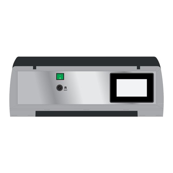
Composition The Master panel consists of: - Wired panel - 1 NTC probe for boiler connection - 2 Wieland plugs for connection to the burner - 1 external probe - 1 NTC probe for SR connection - Technical connection instructions (boiler flow sensor) - 1 NTC probe for Cascade connection - Technical connection instructions... -
Page 5: Connection Detail
Connection Detail BMM: BMM: Connection between Master / Slave Panels Burner connection eBUS BOILER 3-8 Slave BR e R +24V BK GND eBUS BOILER 2 Slave B5 T6 T7 T8 L1 PE N T1 T2 S3 B4 lave lave lave lave lave eBUS... - Page 6 BMM: Safety connections on BMM for cascade boilers BMM Slave panel BMM Master panel SAFETY SAFETY 1 2 3 4 1 2 3 4 Boiler 1 Boiler 2 BCM: Safety connections on BCM for single BCM: Room thermostat / start stop boiler connections SAFETY...
- Page 7 BCM: FL Flow switch connections BCM: Connections SE External probe 12 11 10 9 8 7 6 5 4 3 2 1 12 11 10 9 8 7 6 5 4 3 2 1 +24V +24V BCM (HCM) BCM (HCM) 3 4 5 6 7 3 4 5 6 7 10 11 12 13 14...
- Page 8 Master / Slave general connection diagram SRR SR eBUS BOILER 3-8 BR e R +24V BK GND eBUS BOILER 2 lave lave lave lave lave lave lave R +24V BK GND BR e eBUS 1 2 3 4 1 2 3 1 2 3 4 BK GND PCL PRC...
- Page 9 KIT OPTIONAL SHC SAFETY 8 6 7 6 12 11 10 9 8 7 6 5 4 3 2 1 +24V 1 2 3 4 5 1 2 3 4 5 6 7 8 3 4 5 R +24V 10 1 12 13 14 BK GND 1 2 3 4 5 6 POWE...
- Page 10 Master / Slave connection 1 ... 7 (rotary switches) eBUS BOILER 3-8 Slave BR e R +24V BK GND eBUS BOILER 2 Slave lave lave lave lave lave lave lave eBUS BOILER Master 1 2 3 4 BR e BK GND +24V Master POWE...
- Page 12 Basic scheme (cascade / single BOILER) High temperature boilers / (Condensing boiler see note *) without hydraulic separator slave lave 1 2 3 eBUS 1 2 3 4 5 6 7 1 2 3 1 2 3 eBUS 230 V 230 V 400 V 400 V...
- Page 13 master 230 V (ausiliari) +24V 4 5 6 7 1 2 3 SAFETY +24V 230 V 400 V P.CH Pcar...
- Page 14 Caldaie Alta temperatura / (Caldaia a condensazione vedi nota *) con separatore idraulico (PCL Pompa collettore su BMM) slave lave 1 2 3 eBUS 1 2 3 4 5 6 7 1 2 3 1 2 3 eBUS 230 V 400 V (*) Per caldaie a condensazione non è...
- Page 15 master 230 V (ausiliari) auxiliaries +24V 4 5 6 7 1 2 3 SAFETY +24V 230 V 230 V 400 V 400 V P.CH Pcar...
- Page 16 High temperature boilers / (Condensing boiler see note *) with hydraulic separator (PCL Manifold pump on BMM) slave lave 1 2 3 eBUS 1 2 3 4 5 6 7 1 2 3 1 2 3 eBUS 230 V 230 V 400 V 400 V (*) For condensing boilers, no boiler recir-...
- Page 17 master 230 V auxiliaries (ausiliari) +24V 4 5 6 7 1 2 3 SAFETY +24V 230 V 400 V P.CH Pcoll Pcar...
-
Page 18: Installation Examples
Installation examples BCM secondary circuit Optional SHC secondary circuit Diagram with: Diagram with: 1 High temperature zone CH 2 mixed zones 1 DHW storage tank BCM PARAMETERS PARAMETRI SHC = 16 All services disabled Possibility of 2 mixed zones = 17 Heating only Only CHMix 1 active = 18 Antifreeze only Only CHMix 2 active... -
Page 19: Devices Menu
Burner type configuration From the interface regulator (par.1 pos. 3) The default programming of the MASTER and SLAVE it is necessary to change the parameters panels is: (BMM board) according to the type of bur- TWO-STAGE BURNER (673 Bt = 1) ner and the boiler model HIGH TEMPERATURE BOILER (346 FL = 100) 1 Devices Menu... - Page 20 DEFAULT SETTING (*) high temperature boilers with two-stage burner HCM Board Parameters (BCM) (only for master panel) Code Symbol Description Unit Minimum Maximum Value High 3-point Condensing Condensing temperature modulating boilers with boilers with boilers with burner high two-stage modulating two-stage temperature burner...
- Page 21 BMM board parameters (1/2 / .. for Slave panels) Code Symbol Description Unit Minimum Maximum Value High 3-point Condensing Condensing temperature modulating boilers with boilers with boilers with burner high two-stage modulating two-stage temperature burner burner burner (*) boilers Enabled Services CH#1: Maximum Set-point (Thermostat 100°...
- Page 24 The manufacturer shall not be held liable for any inaccuracies due to transcription or printing errors. Furthermore, it reserves the right to modify its products as deemed necessary or useful, without affecting their essential features.


Need help?
Do you have a question about the MASTER UFLY P and is the answer not in the manual?
Questions and answers