Advertisement
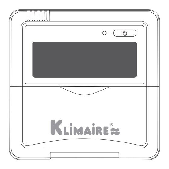
WIRED REMOTE CONTROLLER
Owner's & Installation Manual
MODEL:
KDIP12-H2
KDIP18-H2
KDIP24-H2
IMPORTANT NOTE:
Read this manual carefully before installing or operating your wired
remote controller. Make sure to save this manual for future reference.
/ KDIP036-H2G1 (Series)
/ KDIP048-H2G1 (Series)
/ KDIS060-H2G1 (Series)
Advertisement
Table of Contents

Related Manuals for Klimaire KDIP12-H2 Series


Summary of Contents for Klimaire KDIP12-H2 Series
- Page 1 WIRED REMOTE CONTROLLER Owner’s & Installation Manual MODEL: KDIP12-H2 / KDIP036-H2G1 (Series) KDIP18-H2 / KDIP048-H2G1 (Series) KDIP24-H2 / KDIS060-H2G1 (Series) IMPORTANT NOTE: Read this manual carefully before installing or operating your wired remote controller. Make sure to save this manual for future reference.
-
Page 2: Table Of Contents
Owner’s Manual 1. Remote Control Buttons ........... 1 2. LCD Screen ................4 3. Basic Functions ..............5 4. Troubleshoot your remote control ......15 Installation Manual Wall-Mounted Remote Control Wiring......16 Wall-Mounted Remote Control Installation ....21 Constant Air Volume Testing..........28... -
Page 3: Remote Control Buttons
Remote Control Buttons ON/OFF BUTTON MODE BUTTON • Used to start/stop the air conditioner. • Used to select the operating mode AUTO COOL DRY HEAT FAN ADJUST BUTTON → → → → • The UP (▲) and DOWN • For cooling-only units, there is no (▼)buttons are used to HEAT function. - Page 4 ON/OFF BUTTON MODE BUTTON • Used to start/stop the air conditioner. • Used to select the operating mode AUTO COOL DRY HEAT FAN → → → → • For cooling-only units, there is no ADJUST BUTTON HEAT function. • The UP (▲) and DOWN (▼) TIMER ON BUTTON buttons are used to adjust the temperature.
- Page 5 WARNING DO NOT remove the cover or touch the interior • parts of the remote control. DO NOT use sharp or pointed objects to press • the remote control buttons.
-
Page 6: Lcd Screen
LCD Screen Operation mode Follow me Displays the selected Displayed when the operating mode FOLLOW ME feature is activated ON/OFF Displayed when the air conditioner is Fan speed Displays the selected fan speed Lock Displayed when the LOCK Timer mode is on The “ON”... -
Page 7: Basic Functions
Basic Functions The following are instructions for using your air conditioner’s basic functions. AUTO Function In AUTO mode, the unit will automatically select the COOL, HEAT, FAN or DRY function based on the set temperature. 1 Press the MODE button, select AUTO. 2 Set your desired temperature using the UP ( ) and DOWN ( ) buttons. - Page 8 COOL/HEAT/FAN Function 1 Press the MODE button to select COOL, HEAT or FAN. 2 Set your desired temperature using the UP ( ) and DOWN ( ) buttons. 3 Press the FAN SPEED button to select the fan speed. 4 Press the ON/OFF button to start the unit. NOTE: In FAN mode, the temperature cannot be changed.
- Page 9 DRY Function Press the MODE button, select DRY. Set your desired temperature using the UP ( ) and DOWN ( ) buttons. Press the ON/OFF button to start the unit. NOTE: In DRY mode, the ECONOMY and FAN SPEED buttons cannot be used.
- Page 10 FOLLOW ME Function The FOLLOW ME function enables the remote control to measure the temperature at its current location. When using AUTO, COOL, or HEAT functions, measuring ambient temperature from the remote control (instead of from the indoor unit itself ) will enable the air conditioner to make sure that the temperature around you is optimized for your comfort.
- Page 11 Setting Air Flow Direction 1 Press the SWING button to activate the swing function. Press this button again to set the louver in the position you want. 2 Press and hold the SWING button for three seconds to make the louver move continuously. NOTE: The swing function can only be used in SWING mode.
- Page 12 TIMER Function Your air conditioning unit has two timer-related functions: TIMER ON – sets the amount of time after which the • unit will automatically turn on. (Delayed on) TIMER OFF – sets the amount of time after which the •...
- Page 13 Example: Setting unit to turn on after 2.5 hours. TIMER TIMER Fig. 9 TIMER OFF Function The TIMER OFF function allows you to set a period of time after which the unit will automatically turn o , such as when you wake up. Example: Setting unit to turn on after 5 hours.
- Page 14 Setting both TIMER ON and TIMER OFF at the same time (Combined Timer Function) Keep in mind that the time periods you set for both functions refer to hours after the current time. For example, say that the current time is 1:00 PM, and you want the unit to turn on automatically at 7:00 PM.
- Page 15 TIMER TIMER TIMER TIMER Fig. 11...
- Page 16 The unit will now turn on after 6 hours (7:00 PM) and turn o again after 8 hours (9:00 PM). (See Fig. 11) Your remote display Timer is set to turn ON 6 hours from current time Timer is set to turn OFF 8 hours from current time Unit turns Unit turns...
-
Page 17: Troubleshoot Your Remote Control
Troubleshoot Your Remote Control Symptoms Possible Causes Solution In AUTO mode, the fan speed is Check whether AUTO set automatically and cannot be mode is selected. The fan speed changed. cannot be changed. In DRY mode, the FAN SPEED Check whether DRY button is ine ective. -
Page 18: Wall-Mounted Remote Control Wiring
Wall-Mounted Remote Control Wiring WARNING The wiring should adapt to the wire control current. • Otherwise, electric leakage or overheating may occur and result in fire. The specified cables shall be used in the wiring. No • external force may be applied to the terminal. Otherwise, the wire may be damaged and heating may occur and result in fire. - Page 19 An overview of the wall-mounted remote control wire outlet Top side wire outlet Left side Right side wire outlet wire outlet Bottom side wire outlet Fig. 1 1. Wiring diagram Refer to the following diagram to wire the wall-mounted remote control to the indoor unit. Wire Joint, 5p Infrared Pipe 5-Core Shield Cable...
- Page 20 2. Installation Diagram Connect the wire from the display panel of the indoor unit to a connecting cable. Then connect the other side of the connecting cable to the remote control. The connective wires group 5-core wire Front grille shielded wire(some units) Fig.
- Page 21 NOTE:DO NOT allow water to enter the remote control. Use the trap and putty to seal the wires. Putty Trap Putty Putty Trap Trap Fig. 4 a. For exposed mounting, cut holes on four of the sides according to Fig. 5. b.
- Page 22 Cut one hole for wire outlet Fig. 5 Embedded switch box wiring Wiring through the wall Wall hole and wiring hole Wiring hole Diameter of wall hole: Φ 2cm Fig. 6...
-
Page 23: Wall-Mounted Remote Control Installation
Wall-Mounted Remote Control Installation WARNING DO NOT operate the unit with wet hands, as this could lead to electrical shock. Remote Control Dimensions 120mm 21mm 13.1mm (4.7”) (0.8”) (0.5”) 19.5mm (0.7”) 120mm 85.5mm (4.7”) (3.3”) 50mm (1.9”) MODEL A Fig. 7a... - Page 24 Remote Control Dimensions 120mm 21mm 13.1mm (4.7”) (0.8”) (0.5”) 19.5mm (0.7”) 120mm 85.5mm (4.7”) (3.3”) 50mm (1.9”) MODEL B Fig. 7b...
- Page 25 Preparation Before Installation 1. Ensure you have the following parts Table 1 Name Quantity Remarks Remote Control Screws ST3.9*19 (For mounting on the wall) Anchors For mounting on the wall Screws M4X25 (For mounting on switch box) Screws ST3.9*12 Plastic screw bars For fixing on switch box (some models) The connective some models...
- Page 26 Installation Method Remove the top panel of remote control Insert a screwdriver into the two slots at the bottom of the remote control to pop o the top panel. Slots Fig. 8 NOTE: The Printed Circuit Board (PCB) is mounted in the upper part of the remote control.
- Page 27 2. Mount the back plate of the remote control For exposed mounting, fasten the back plate to the wall with 3 screws (ST3.9*19) and anchors. Back plate Screws (ST3.9*19) MODEL A Fig. 9a Back plate Screws (ST3.9*19) MODEL B Fig. 9b...
- Page 28 For flush mounting, fasten the back plate to the switch box with 2 screws (M4×25), and fasten the back plate to the wall with 1 screw (ST3.9*19). Switch box Back plate Screw (ST3.9*19) Screws (M4×25) MODEL A Fig. 10a Switch box Back plate Screw (ST3.9*19) Screws (M4×25)
- Page 29 3. Set the time and date The remote control has a small, built-in battery that allows the time and date to be set. That way the remote control can keep time even during a power outage. When the unit displays an incorrect time and date the batteries need to be replaced.
-
Page 30: Constant Air Volume Testing
Constant air volume testing (To set external static pressure) (some models) • You can use the unit’s automatic air ow adjustment function to set external static pressure. • Automatic air ow adjustment is the volume of blow-o air that has been automatically adjusted to the quantity rated. - Page 31 ①When the unit is turned o , hold the MODE button and FAN button down together for three seconds. ("AF" indicator ashes for 3 times.) ②Press “△” or “▽” to select the AF. ③Press “MODE”. The air conditioning unit will then start the fan for air ow automatic adjustment.
- Page 32 Using the wire controller to set air ow rate (some models) When the air conditioning unit is o , perform the follwoing steps: ①Press“MODE” and "FAN" for three seconds. ②Press “△” or “▽” to select the SP. ③Press “MODE” to set the air ow rate in the range of 0~4.
- Page 33 The Klimaire logo is a registered Trademark of Klimaire Products inc. Copyright 2022 Klimaire Products lnc. 2190 NW 89 Place, Doral, FL 33172 - USA Tel: (305)593-8358 Fax (305) 675-2212 www.klimaire.com sales@klimaire.com The design and specifications are subject to change without prior notice for product...
Need help?
Do you have a question about the KDIP12-H2 Series and is the answer not in the manual?
Questions and answers