Advertisement
- 1 PRODUCT INTRODUCTION
- 2 LED RING LIGHT STATUS
- 3 WHAT'S IN THE BOX
- 4 TOOLS NEEDED
- 5 CHECK COMPATIBILITY
- 6 BEFORE WE START
- 7 REMOVE OLD SWITCH
- 8 IDENTIFY THE TYPE OF CIRCUIT
- 9 WIRING DIAGRAM FOR PRO
- 10 DISCONNECT THE SWITCH TO LOAD
- 11 STRIP WIRES
- 12 HOW TO USE WIRE CONNECTORS
- 13 CONNECT WIRES
- 14 FINISH WIRING
- 15 MOUNT WALL PLATE
- 16 COVERAGE PATTERNS
- 17 TROUBLESHOOTING
- 18 Documents / Resources
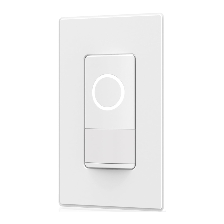
PRODUCT INTRODUCTION

LED RING LIGHT STATUS
| White | Auto Mode (Sensors are activated) The switch will be either auto-on when a human is detected or auto-off when the space is vacant. |
| Blue | Manual Mode (Sensors are disabled) The switch could only be manually switched on and off. |
| Green | Testing Sensors |
| Flashing White | Connecting to Wi-Fi |
| Orange | Disconnected from Wi-Fi |
WHAT'S IN THE BOX

TOOLS NEEDED

CHECK COMPATIBILITY
Compatible Bulb Types

Max Load for Each Bulb Type
| Bulb Type | LED / CFL | INC / HAL |
| Max Load | 150W | 450W |
Rating: 120VAC, 60Hz
Operating Temperature: 0℃~40℃ (32℉~104℉)
Storage Temperature: -40℃~60℃ (-40℉~140℉)
Wiring Type: 3-Way
Type of Action: Type 1.Y Action
Protection Level: Type I Insulation
 The white neutral wire is required to connect. The device will not function if the neutral wire is not connected.
BEFORE WE START

To avoid fire, shock, or death, turn off power at circuit breaker or fuse and test that the power is off before wiring!

To reduce the risk of overheating and possible damage to other equipment, DO NOT install to control a receptacle, a motor operated appliance, a fluorescent lighting fixture, or a transformer-supplied appliance.
Consult a qualified electrician if you are unfamiliar with electrical codes and regulations, or are uncomfortable performing the installation.
REMOVE OLD SWITCH

After power is turned off, remove wall plate and switch mounting screws. Carefully pull out the old switch from the wall box (do not remove wires).
 Turn Off Power
Before removing, turn off power at circuit breaker or fuse and use a test pencil to confirm whether power is off before wiring or servicing fixture!
IDENTIFY THE TYPE OF CIRCUIT

| Wire Label | Line | Load | Neutral | Ground | Traveler T1 | Traveler T2 |
| Wire Color | Black | Red or Black | White | Green or Bare Copper | unknown | unknown |
- Turn ON the power from circuit breaker and switch OFF the light(s).
- Turn on the test pencil and pass it through the wires connected to the common terminals (usually black) in each wall box. Blinking and beeping indicate Line wire from the wall box to Power Source. The non-response wire is the Load wire from the wall box to Load (Fixture).
- Pass the test pencil through the other traveler terminals (usually brass) from each wall box. Blinking and beeping indicate Traveler 1. The non-response wire is Traveler 2.
- Turn OFF the power from circuit breaker. Label the Line, Load, Traveler 1 and Traveler 2 wires from each wall box as previously identified.
- Label the Neutral wire and Ground wire in each wall box. Neutral wires are usually white, and Ground wires are usually green / bare copper.
This smart device should be installed in the wall box that is connected to the Load (Fixture) and has a NEUTRAL wire (usually white) available.
WIRING DIAGRAM FOR PRO

If the Neutral wire exists in the wall box to Power Source only, and the wiring in the wall box does not resemble any of these configurations, check this wiring diagram and consult a qualified electrician.
DISCONNECT THE SWITCH TO LOAD
Disconnect the switch from the wall box to Load (Fixture).
Do not remove the original switch from the wall box connected to Power Source.
STRIP WIRES
Make sure that the ends of the disconnected wires from the wall box are straight (cut if necessary).
Remove 0.6" (15mm) of insulation from each wire in the wall box.

HOW TO USE WIRE CONNECTORS
- Insert wire into wire connectors.
- Turn wire connectors clockwise.
- Pull gently on wires to test connection.
![]()

For non-standard wiring applications, refer to the following Wire Connector Size Chart:
| WIRE CONNECTOR / # OF COND. COMBINATION CHART |
| 1-#14 w/ 1 to 2 #16 or #18 1-#16 w/ 1 to 2 #16 or #18 1-#18 w/ 1 to 3 #18 |
CONNECT WIRES

For the original 3-way switch in the location connected to the Power Source
- Disconnect the Traveler 1 from the original 3-way switch.
- Connect the Traveler 1 to the terminal screw on the switch marked "Common", where there was a black wire labeled "Line".
For the smart switch in the location connected to the Load (Fixture)
- Check the wire identifications from the back of the smart device.
- Match every labeled wire from the wall box with the wires of the smart device.
- Screw on the provided wire connectors clockwise to connect wires.
If the smart device is installed in a single-pole circuit, do not connect the 3-way wire of the smart device.
FINISH WIRING

Form all wires carefully into wall box, and mount switch with mounting screws supplied.
MOUNT WALL PLATE

Push a flat-head screwdriver into the slot at the bottom of the faceplate. Gently pry apart the two pieces.
Use the short screws to mount the fixing plate.
Push faceplate onto the fixing plate and snap it into place.
COVERAGE PATTERNS
In open space, the sensor detects motion in areas up to 600 sq. ft. and up to 26.2 feet from the sensor. Ideally, the Fresnel lens on the sensor is a multiple segment viewing lens with a field of view of 120°. The sensor must have a clear view of the people in the space in order to detect occupancy. Obstructions, such as furniture blocking the sensor's lens, may prevent occupancy detection.
It is recommended to install the smart device at a height between 1.2m to 1.5m for optimal performance.

TROUBLESHOOTING
After installation, the switch does not turn on?
- Check that the bulb is properly installed and has not failed.
- Check if the circuit breaker or fuse is connected properly.
- Try swapping your Line and Load wires.
Difficulty in connecting smart switch to a WiFi network?
- Make sure the WiFi network is a 2.4 GHz network.
- The WiFi connection may not have good coverage. Try moving your WiFi router closer to the smart switch.
Refer to help center in the app for additional troubleshooting suggestions
HAVING PROBLEMS? WE CAN HELP!
Email: support@elegrp.com
Call us on: 866-267-3272
Mon-Fri 9:00-17:00 EST (US)
Feel free to contact us with any questions or concerns. Our customer service team will work hard to put a smile back on your face.
About Us
Website: www.elegrp.com
Search ELEGRP on social media
Documents / Resources
References
Download manual
Here you can download full pdf version of manual, it may contain additional safety instructions, warranty information, FCC rules, etc.
Advertisement


Need help?
Do you have a question about the SSS30 and is the answer not in the manual?
Questions and answers