ASROCK A780FULLHD Installation Manual
Hide thumbs
Also See for A780FULLHD:
- User manual (61 pages) ,
- Installation manual (17 pages) ,
- User manual (192 pages)
Table of Contents
Advertisement
Available languages
Available languages
Quick Links
Download this manual
See also:
User Manual
Copyright Notice:
Copyright Notice:
Copyright Notice:
Copyright Notice:
Copyright Notice:
No part of this installation guide may be reproduced, transcribed, transmitted, or trans-
lated in any language, in any form or by any means, except duplication of documen-
tation by the purchaser for backup purpose, without written consent of ASRock Inc.
Products and corporate names appearing in this guide may or may not be registered
trademarks or copyrights of their respective companies, and are used only for identifica-
tion or explanation and to the owners' benefit, without intent to infringe.
Disclaimer:
Disclaimer:
Disclaimer:
Disclaimer:
Disclaimer:
Specifications and information contained in this guide are furnished for informational
use only and subject to change without notice, and should not be constructed as a
commitment by ASRock. ASRock assumes no responsibility for any errors or omissions
that may appear in this guide.
With respect to the contents of this guide, ASRock does not provide warranty of any kind,
either expressed or implied, including but not limited to the implied warranties or
conditions of merchantability or fitness for a particular purpose. In no event shall
ASRock, its directors, officers, employees, or agents be liable for any indirect, special,
incidental, or consequential damages (including damages for loss of profits, loss of
business, loss of data, interruption of business and the like), even if ASRock has been
advised of the possibility of such damages arising from any defect or error in the guide
or product.
This device complies with Part 15 of the FCC Rules. Operation is subject to the
following two conditions:
(1) this device may not cause harmful interference, and
(2) this device must accept any interference received, including interference that
may cause undesired operation.
CALIFORNIA, USA ONLY
The Lithium battery adopted on this motherboard contains Perchlorate, a toxic
substance controlled in Perchlorate Best Management Practices (BMP) regulations
passed by the California Legislature. When you discard the Lithium battery in
California, USA, please follow the related regulations in advance.
"Perchlorate Material-special handling may apply, see
www.dtsc.ca.gov/hazardouswaste/perchlorate"
ASRock Website: http://www.asrock.com
Copyright©2008 ASRock INC. All rights reserved.
ASRock
Published July 2008
A780FullHD
Motherboard
1 1 1 1 1
Advertisement
Table of Contents

Related Manuals for ASROCK A780FULLHD

Summary of Contents for ASROCK A780FULLHD
- Page 1 ASRock. ASRock assumes no responsibility for any errors or omissions that may appear in this guide. With respect to the contents of this guide, ASRock does not provide warranty of any kind, either expressed or implied, including but not limited to the implied warranties or conditions of merchantability or fitness for a particular purpose.
-
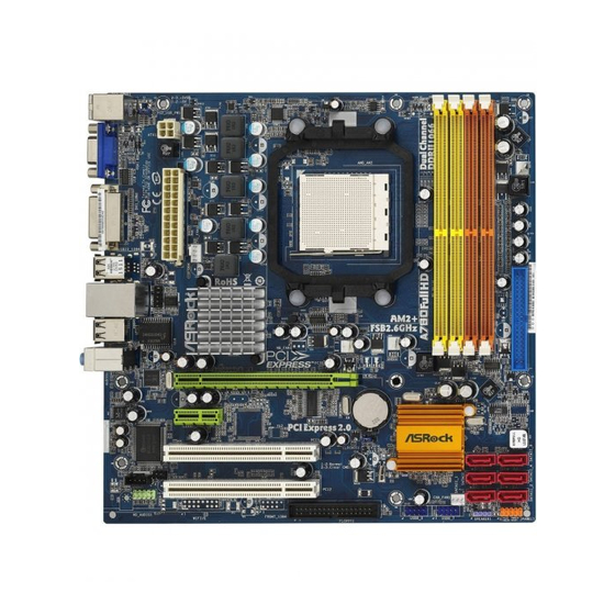
Page 2: Motherboard Layout
Infrared Module Header (IR1) Fifth SATAII Connector (SATAII_5 (PORT4)) PCI Slots (PCI1- 2) SPI Flash Memory (8Mb) PCI Express 2.0 x1 Slot (PCIE2; Green) Sixth SATAII Connector (SATAII_6 (PORT5)) PCI Express 2.0 x16 Slot (PCIE1; Green) Third SATAII Connector (SATAII_3 (PORT2)) -
Page 3: Asrock Dvi I/O Plus
PS/2 Keyboard Port (Purple) Front Speaker (Lime) * To enable Multi-Streaming function, you need to connect a front panel audio cable to the front panel audio header. Please refer to below steps for the software setting of Multi-Streaming. For Windows ®... -
Page 4: Package Contents
ASRock’s commitment to quality and endurance. In this manual, chapter 1 and 2 contain introduction of the motherboard and step-by-step guide to the hardware installation. Chapter 3 and 4 contain the configuration guide to BIOS setup and information of the Support CD. -
Page 5: Specifications
- Solid Capacitor for CPU power - Support for Socket AM2+ / AM2 processors: AMD Phenom FX / Phenom / Athlon 64 FX / Athlon 64 X2 Dual-Core / Athlon X2 Dual-Core / Athlon 64 / Sempron processor - Supports CPU up to 140W... - Page 6 - 1 x RJ-45 Port - HD Audio Jack: Line in/Front Speaker/Microphone Connector - 6 x Serial ATAII 3.0Gb/s connectors, support RAID (RAID 0, RAID 1, RAID 10 and JBOD), NCQ, AHCI and “Hot Plug” functions (see CAUTION 7) - 1 x ATA133 IDE connector (supports 2 x IDE devices)
- Page 7 Overclocking may affect your system stability, or even cause damage to the components and devices of your system. It should be done at your own risk and expense. We are not responsible for possible damage caused by overclocking.
- Page 8 13. This motherboard supports ASRock AM2 Boost overclocking technology. If you enable this function in the BIOS setup, the memory performance will improve up to 12.5%, but the effect still depends on the AM2 CPU you adopt. Enabling this function will overclock the chipset/CPU reference clock. However, we can not guarantee the system stability for all CPU/DRAM configurations.
-
Page 9: Premium 2008 And Basic Logo
Premium or Basic logo, please adjust the shared memory size of onboard VGA to 128MB or above. * If you plan to use external graphics card on this motherboard, please refer to Premium Discrete requirement at http://www.asrock.com * If the onboard VGA supports DVI, it must also support HDCP function to qualify for Windows ®... -
Page 10: Minimum Hardware Requirement For 1080P Blu-Ray (Bd) / Hd-Dvd Playback Support
Vista or Windows Vista * If you need to use CyberLink PowerDVD Ultra version 7.3, we suggest to disable Hardware Acceleration function for better playback performance and compatibility. After executing CyberLink PowerDVD Ultra program, please follow below steps to disable Hardware Acceleration function. - Page 11 ONE SIX RIGHT MPEG-2 TERWILLIGER THE INTERPRETER MPEG-4-AVC UNIVERSAL * MPEG-4-AVC mentioned above refers to the same format of H.264. * Above passed films are tested under below configuration. Items Configurations AMD Athlon X2 3600 Onboard VGA with DVI-D port...
-
Page 12: Pre-Installation Precautions
Installation Installation Installation This is a Micro ATX form factor (9.6-in x 9.6-in, 24.4 cm x 24.4 cm) motherboard. Before you install the motherboard, study the configuration of your chassis to en- sure that the motherboard fits into it. Pre-installation Precautions... -
Page 13: Installation Of Cpu Fan And Heatsink
Step 4. When the CPU is in place, press it firmly on the socket while you push down the socket lever to secure the CPU. The lever clicks on the side tab to indicate that it is locked. -
Page 14: Installation Of Memory Modules (Dimm)
(the same brand, speed, size and chip- type) DDR2 DIMM pair in the slots of the same color. In other words, you have to install identical DDR2 DIMM pair in Dual Channel A (DDRII_1 and DDRII_2;... -
Page 15: Installing A Dimm
Unlock a DIMM slot by pressing the retaining clips outward. Step 2. Align a DIMM on the slot such that the notch on the DIMM matches the break on the slot. The DIMM only fits in one correct orientation. It will cause permanent damage to the motherboard and the DIMM if you force the DIMM into the slot at incorrect orientation. -
Page 16: Expansion Slots (Pci And Pci Express Slots)
2.4 Expansion Slots (PCI and PCI Express Slots) 2.4 Expansion Slots (PCI and PCI Express Slots) There are 2 PCI slots and 2 PCI Express slots on this motherboard. PCI slots: PCI slots are used to install expansion cards that have the 32-bit PCI interface. PCIE slots: PCIE1 (PCIE x16 slot) is used for PCI Express cards with x16 lane width graphics cards. -
Page 17: Dual Monitor And Surround Display Features
VGA/D-Sub port VGA/DVI-D port 2. If you have installed onboard VGA driver from our support CD to your system already, you can freely enjoy the benefits of dual monitor function after your system boots. If you haven’t installed onboard VGA driver yet, please install onboard VGA driver from our support CD to your system and restart your computer. - Page 18 [512MB] to enable the function of VGA/D-sub. Please make sure that the value you select is less than the total capability of the system memory. If you do not adjust the BIOS setup, the default value of “Share Memory”, [Auto], will disable VGA/D-Sub function when the add-on VGA card is inserted to this motherboard.
- Page 19 - such as a computer, DVD player or set-top box - and the digital display, or receiver - such as a monitor, television or projector. In other words, HDCP specification is designed to protect the integrity of content as it is being transmitted.
- Page 20 Catalyst 8.47 256MD2-S * Currently, RADEON HD2400XT series graphics cards are only supported with AMD Phenom CPU. Please visit our website for the future driver update and the latest information. Enjoy the benefit of A Enjoy the benefit of A...
- Page 21 * Hybrid CrossFireX appearing here is a registered trademark of ATI Technologies Inc., and is used only for identification or explanation and to the owners’ benefit, without intent to infringe. * For further information of ATI Hybrid CrossFireX technology, please check AMD website for up dates and details.
-
Page 22: Jumpers Setup
After waiting for 15 seconds, use a jumper cap to short pin2 and pin3 on CLRCMOS1 for 5 seconds. However, please do not clear the CMOS right after you update the BIOS. -
Page 23: Onboard Headers And Connectors
(33-pin FLOPPY1) (see p.2 No. 25) the red-striped side to Pin1 Note: Make sure the red-striped side of the cable is plugged into Pin1 side of the connector. Primary IDE connector (Blue) (39-pin IDE1, see p.2 No. 10) connect the black end... - Page 24 HDA to function correctly. Please follow the instruction in our manual and chassis manual to install your system. 2. If you use AC’97 audio panel, please install it to the front panel audio header as below: A.
- Page 25 ® For Windows XP / XP 64-bit OS: Please select “Front Mic” as default record device. If you want to hear your voice through front mic, please deselect "Mute" icon in “Front Mic” of “Playback” portion. ® For Windows Vista...
- Page 26 Though this motherboard provides 4-Pin CPU fan (Quiet Fan) support, the 3-Pin CPU fan still can work successfully even without the fan speed control function. If you plan to connect the 3-Pin CPU fan to the CPU fan connector on this motherboard, please connect it to Pin 1-3.
- Page 27 STEP 4: Connect the other end of the SATA data cable to the SATA / SATAII hard disk. If you plan to use RAID 0 or RAID 1 function, you need to install at least 2 SATA / SATAII hard disks. If you plan to use RAID 10 function, you need to install 4 SATA / SATAII hard disks.
-
Page 28: Installing Windows Vista
2.10 Driver Installation Guide To install the drivers to your system, please insert the support CD to your optical drive first. Then, the drivers compatible to your system can be auto-detected and listed on the support CD driver page. Please follow the order from up to bottom side to install those required drivers. - Page 29 64-bit OS on your system. When you see “Where do you want to install Windows?” page, please insert the ASRock Support CD into your optical drive, and click the “Load Driver” button on the left on the bottom to load the AMD AHCI ASRock...
-
Page 30: Untied Overclocking Technology
Untied Overclocking function, please enter “Overclock Mode” option of BIOS setup to set the selection from [Auto] to [CPU, PCIE, Async.]. Therefore, CPU FSB is untied during overclocking, but PCI / PCIE buses are in the fixed mode so that FSB can operate under a more stable overclocking environment. -
Page 31: Bios Information
To begin using the Support CD, insert the CD into your CD-ROM drive. It will display the Main Menu automatically if “AUTORUN” is enabled in your computer. If the Main Menu does not appear automatically, locate and double-click on the file “ASSETUP. - Page 32 ASRock A780FullHD Motherboard...
- Page 33 ‘ ’ ® ASRock A780FullHD Motherboard...
- Page 34 ASRock A780FullHD Motherboard...
- Page 35 ® ® ® ® ® ® ® ® ASRock A780FullHD Motherboard...
- Page 36 ® ® ® ® ® ® ® ASRock A780FullHD Motherboard...
- Page 37 ASRock A780FullHD Motherboard...
- Page 38 ASRock A780FullHD Motherboard...
- Page 39 DDRII_1 DDRII_2 DDRII_3 DDRII_4 ASRock A780FullHD Motherboard...
- Page 40 ASRock A780FullHD Motherboard...
- Page 41 ASRock A780FullHD Motherboard...
- Page 42 ASRock A780FullHD Motherboard...
- Page 43 ® ® ASRock A780FullHD Motherboard...
- Page 44 ® ASRock A780FullHD Motherboard...
- Page 45 ® ® ® ® ® ASRock A780FullHD Motherboard...
- Page 46 View Enable CrossFire CrossFire ASRock A780FullHD Motherboard...
- Page 47 CrossFire ASRock A780FullHD Motherboard...
- Page 48 SATAII_5 SATAII_6 (PORT4) (PORT5) SATAII_3 SATAII_4 (PORT2) (PORT3) SATAII_1 SATAII_2 (PORT0) (PORT1) ASRock A780FullHD Motherboard...
- Page 49 ® ® ® ® ASRock A780FullHD Motherboard...
- Page 50 ASRock A780FullHD Motherboard...
- Page 51 ASRock A780FullHD Motherboard...
- Page 52 ® ® ® ® ® ® ® ® ® ® ® ® ® ® ASRock A780FullHD Motherboard...
- Page 53 ® ® ® ® ® ® ASRock A780FullHD Motherboard...
- Page 54 ® ® ® ® ® ® ® ® ® ® ® ® ® ® ASRock A780FullHD Motherboard...
- Page 55 ® ® ASRock A780FullHD Motherboard...
- Page 56 ASRock A780FullHD Motherboard...
- Page 57 Wir danken Ihnen für den Kauf des ASRock A780FullHD Motherboard, ein zuverlässiges Produkt, welches unter den ständigen, strengen Qualitätskontrollen von ASRock gefertigt wurde. Es bietet Ihnen exzellente Leistung und robustes Design, gemäß der Verpflichtung von ASRock zu Qualität und Halbarkeit.
-
Page 58: Spezifikationen
1 . 2 Spezifikationen Spezifikationen Plattform - Micro ATX-Formfaktor: 24.4 cm x 24.4 cm; 9.6 Zoll x 9.6 Zoll - Festkondensator für CPU-Leistung - Unterstützung für Socket AM2+ / AM2-Prozessoren: AMD Phenom FX / Phenom / Athlon 64 FX / Athlon 64 X2 Dualkern / Athlon X2 Dualkern / Athlon 64 / Sempron-Prozessor - Unterstützt CPU bis 140W... - Page 59 Anschlüsse - 6 x SATAII-Anschlüsse, unterstützt bis 3.0 Gb/s Datenübertragungsrate, unterstützt RAID (RAID 0, RAID 1, RAID 10 und JBOD), NCQ, AHCI und “Hot Plug” Funktionen (siehe VORSICHT 7) - 1 x ATA133 IDE-Anschlüsse (Unterstützt bis 2 IDE-Geräte) - 1 x FDD-Anschlüsse...
- Page 60 Beachten Sie bitte, dass Overclocking, einschließlich der Einstellung im BIOS, Anwenden der Untied Overclocking-Technologie oder Verwenden von Overclocking-Werkzeugen von Dritten, mit einem gewissen Risiko behaftet ist. Overclocking kann sich nachteilig auf die Stabilität Ihres Systems auswirken oder sogar Komponenten und Geräte Ihres Systems beschädigen.
- Page 61 1080p Blu-ray (BD)/HD-DVD Playback Unterstützung auf dieser Hauptplatine fordert die passende Hardwarekonfiguration. Bitte verweisen Sie auf Seite 10 und 11 für minimal Hardware Anforderung und die überschritten 1080p Blu-ray (BD)/HD-DVD Filme in unserem Laborversuch. Vor Installation der SATAII-Festplatte an den SATAII-Anschluss lesen Sie bitte “Setup-Anleitung für SATAII-Festplatte”...
- Page 62 Arbeitsspeichers auf 128MB oder noch mehr ein. Sofern Sie eine externe Grafikkarte mit diesem Motherboard verwenden möchten, lesen Sie bitte unter Premium Discrete-Anforderungen auf unseren Internetseiten nach: http://www.asrock.com Wenn VGA auf der Platte DVI unterstützt, muß es auch HDCP Function ® unterstützen, um Windows Vista Premium 2008 logo.zu befähigen.
-
Page 63: Installation
2. Installation 2. Installation 2. Installation Dies ist ein Motherboard mit einem Micro ATX-Formfaktor (9,6 Zoll x 9,6 Zoll, 24,4 cm x 24,4 cm). Vor Installation des Motherboards müssen Sie die Konfiguration Ihres Gehäuses dahingehend überprüfen, ob das Motherboard dort hineinpasst. - Page 64 2.1 CPU Installation 2.1 CPU Installation Schritt 1: Öffnen Sie den CPU-Sockel, indem sie den Hebel leicht zur Seite und dann nach oben ziehen, auf einen Winkel von 90°. Schritt 2: Positionieren Sie die CPU genau so über dem Sockel, dass sich die Ecke der CPU mit dem goldenen Dreieck exakt über der Ecke des...
- Page 65 Steckplätzen gleicher Farbe installieren. Mit anderen Worten, sie müssen ein identisches DDR2 DIMM-Paar im Dual-Kanal A (DDRII_1 und DDRII_2; gelbe Steckplätze, siehe Seite 2 Nr. 8) oder ein identisches DDR2 DIMM-Paar im Dual- Kanal B (DDRII_3 und DDRII_4; orange Steckplätze, siehe Seite 2 Nr. 9) installieren, damit die Dual-Kanal-Speichertechnologie aktiviert werden kann.
- Page 66 Öffnen Sie einen DIMM-Slot, indem Sie die seitlichen Clips nach außen drücken. Schritt 2: Richten Sie das DIMM-Modul so über dem Slot aus, dass das Modul mit der Kerbe in den Slot passt. Die DIMM-Module passen nur richtig herum eingelegt in die Steckplätze.
- Page 67 Gehäuseschacht (Slot) , den Sie nutzen möchten und behalten die Schraube für den Einbau der Karte. Schritt 3: Richten Sie die Karte über dem Slot aus und drücken Sie sie ohne Gewalt hinein, bis sie den Steckplatz korrekt ausfüllt. Schritt 4: Befestigen Sie die Karte mit der Schraube aus Schritt 2.
- Page 68 Sie in der Lage, die Dual-Monitorfunktion auf diesem Motherboard zu verwenden. Als Sie HDCP-schützten Video von Blu-ray (BD) oder HD-DVD Platte abspielen, wird der Inhalt nur in einem der zwei Monitoren anstelle in beiden Monitoren angezeigt. Surround-Display-Funktion Dieses Motherboard unterstutzt Surround-Display-Aufrustung. Mit Unterstutzung des...
- Page 69 Quality (Farbtiefe für den zweiten Monitor ein) “. Klicken Sie auf „Apply (Übernehmen)“ oder „OK“, um die neuen Werte zu übernehmen. G. Wiederholen Sie die Schritte C bis E für die mit den Ziffern Eins, Zwei, Drei und Vier gekennzeichneten Anzeigegeräte.
- Page 70 (Arbeitsplatz auf diesen Monitor erweitern). C. Klicken Sie „OK“, um Ihre Änderungen zu speichern. D. Wiederholen Sie die Schritte A bis C für das durch die Nummern drei und vier gekennzeichnete Displaysymbol. 6. Verwenden Sie Surround-Display. Klicken Sie die Anzeige-Symbole an und ziehen Sie sie in die räumliche Position, in der Sie sie benutzen möchten.
- Page 71 -System enthält einen Grafikprozessor der ATI Radeon 2400- oder ATI Radeon 3450-Serie sowie ein Motherboard, das auf einen im AMD 780G integrierten Chipsatz basiert, wobei alles in einer Windows ® Vista -Umgebung funktioniert. Beziehen Sie sich hinsichtlich ATI Hybrid CrossFireX auf die nachstehende Liste unterstützter PCI Express-Grafikkarten.
- Page 72 Schritt 8. Klicken Sie auf “Yes” (Ja), um fortzufahren. Schritt 9. Klicken Sie auf “OK”, um Ihre Änderung zu speichern. Schritt 10. Starten Sie Ihr System neu. Sie können jetzt über die Vorteile der Hybrid CrossFireX -Funktion frei verfügen. ASRock...
- Page 73 * Das hier angegebene Hybrid CrossFireX ist ein eingetragenes Markenzeichen der ATI Technologies Inc. und wird nur zum Zweck der Identifizierung oder Erklärung und zum Nutzen der Besitzer verwendet, ohne irgendwelche Rechte verletzen zu wollen. * Informieren sich über weitere Updates und Details der ATI Hybrid CrossFireX Technologie bei einem Besuch der AMD-Website.
- Page 74 (33-Pin FLOPPY1) die rotgestreifte Seite auf Stift 1 (siehe S.2, No. 25) Hinweis: Achten Sie darauf, dass die rotgestreifte Seite des Kabel mit der Stift 1- Seite des Anschlusses verbunden wird. Primärer IDE-Anschluss (blau) (39-pin IDE1, siehe S.2, No. 10)
- Page 75 1. High Definition Audio unterstützt Jack Sensing (automatische Erkennung falsch angeschlossener Geräte), wobei jedoch die Bildschirmverdrahtung am Gehäuse HDA unterstützen muss, um richtig zu funktionieren. Beachten Sie bei der Installation im System die Anweisungen in unserem Handbuch und im Gehäusehandbuch. ASRock...
- Page 76 E. Rufen Sie das BIOS-Setup-Dienstprogramm auf. Wechseln Sie zu Erweiterte Einstellungen und wählen Sie Chipset-Konfiguration. Setzen Sie die Option Frontleistenkontrolle von [Automatisch] auf [Aktiviert]. F. Rufen Sie das Windows-System auf. Klicken Sie auf das Symbol in der Taskleiste unten rechts, um den Realtek HD Audio-Manager aufzurufen. Für Windows ®...
- Page 77 Obwohl dieses Motherboard einen 24-pol. ATX-Stromanschluss bietet, kann es auch mit einem modifizierten traditionellen 20-pol. ATX-Netzteil verwendet werden. Um ein 20-pol. ATX-Netzteil zu verwenden, stecken Sie den Stecker mit Pin 1 und Pin 13 ein. Installation eines 20-pol. ATX-Netzteils Anschluss für...
- Page 78 Anschließend werden die mit Ihrem System kompatiblen Treiber automatisch erkannt und auf dem Bildschirm angezeigt. Zur Installation der nötigen Treiber gehen Sie bitte der Reihe nach von oben nach unten vor. Nur so können die von Ihnen installierten Treiber richtig arbeiten.
-
Page 79: Installation Von Windows
XP / XP 64-bit / Vista / Vista 64-bit auf Ihren SATA- / SATAII-Festplatten mit RAID-Funktionalität installieren möchten, entnehmen Sie die detaillierten Schritte bitte dem Dokument, das Sie unter folgendem Pfad auf der Unterstützungs-CD finden: ..\ RAID Installation Guide 2.12 2.12... - Page 80 Sie zum Beginnen eine beliebige Taste.) Bitte legen Sie eine Diskette in das Diskettenlaufwerk ein und drucken Sieeine beliebige Taste. Das System beginnt mit dem Formatieren der Diskette und kopiert die SATA / SATAII-Treiber auf die Diskette. ®...
- Page 81 Setzen Sie die Option “SATA Operation Mode” (SATA-Betriebsmodus) auf [AHCI]. SCHRITT 2: Erstellen Sie eine SATA / SATAII-Treiberdiskette. Erstellen Sie, wie auf Seite 79 in Kapitel 2.12.1 Schritt 2 beschrieben, eine SATA / SATAII-Treiberdiskette. SCHRITT 3: Installieren Sie Windows ®...
- Page 82 Dieses Motherboard unterstützt die Entkoppelte Übertaktungstechnologie, durch die der FSB durch fixierte PCI-/PCIE-Busse beim Übertakten effektiver arbeiten. Bevor Sie die Entkoppelte Übertaktung aktivieren, stellen Sie bitte die Option “Overclock Mode” (Übertaktungsmodus) im BIOS von [Auto] auf [CPU, PCIE, Async.] um. Dadurch wird der CPU-FSB beim Übertakten entkoppelt, PCI- und PCIE-Busse werden jedoch fixiert, so dass der FSB in einer stabileren Übertaktungsumgebung arbeiten kann.
- Page 83 Wilkommensbildschirm nicht, so “doppelklicken” Sie bitte auf das File ASSETUP. EXE im BIN-Verzeichnis der Support-CD, um die Menüs aufzurufen. Das Setup- Programm soll es Ihnen so leicht wie möglich machen. Es ist menügesteuert, d.h. Sie können in den verschiedenen Untermenüs Ihre Auswahl treffen und die Programme werden dann automatisch installiert.
-
Page 84: Contenu Du Paquet
Contenu du paquet Contenu du paquet Carte mère ASRock A780FullHD (Facteur de forme Micro ATX: 9.6 pouces x 9.6 pouces, 24.4 cm x 24.4 cm) Guide d’installation rapide ASRock A780FullHD CD de soutien ASRock A780FullHD Un câble ruban IDE Ultra ATA 66/100/133 80 conducteurs Un câble ruban pour un lecteur de disquettes 3,5 pouces... - Page 85 - Prise en charge des processeurs Socket AM2+ / AM2: AMD Phenom FX / Phenom / Athlon 64 FX / Athlon 64 X2 Dual-Core / Athlon X2 Dual-Core / Athlon 64 / processeur Sempron - Supporte les processeurs jusqu’à 140W - Prêt AMD LIVE!
- Page 86 - br. 24 connecteur d’alimentation ATX - br. 4 connecteur d’alimentation 12V ATX - Connecteurs audio internes - Connecteur audio panneau avant - 2 x En-tête USB 2.0 (prendre en charge 4 ports USB 2.0 supplémentaires) (voir ATTENTION 8) BIOS - 8Mb BIOS AMI - BIOS AMI - Support du “Plug and Play”...
- Page 87 64-bit Certifications - FCC, CE, WHQL * Pour de plus amples informations sur les produits, s’il vous plaît visitez notre site web: http://www.asrock.com ATTENTION Il est important que vous réalisiez qu’il y a un certain risque à effectuer l’overclocking, y compris ajuster les réglages du BIOS, appliquer la technologie Untied Overclocking, ou...
- Page 88 Avant d’installer le disque dur SATAII au connecteur SATAII, veuillez lire le Guide « Installation du disque dur SATAII » à la page 30 du « Manuel de l’utilisateur » qui se trouve sur le CD de support pour régler votre lecteur de disque dur SATAII au mode SATAII.
- Page 89 256MB x 2 double canal (Premium) Adaptateur VGA DX10 avec pilote WDDM DVI avec HDCP * Si vous utilisez VGA intégré avec une mémoire système de 512Mo et que vous désirez soumettre le logo de Windows ® Vista Basic, veuillez régler la taille de la mémoire partagée de VGA intégré...
- Page 90 2. Installation 2. Installation Il s’agit d’une carte mère à facteur de forme Micro ATX (9,6 po x 9,6 po, 24,4 cm x 24,4 cm). Avant d’installer la carte mère, étudiez la configuration de votre châssis pour vous assurer que la carte mère s’y insère.
- Page 91 Etape 1. Déverrouillez le support en relevant le levier selon un angle de 90 Etape 2. Placer l’UC directement au-dessus de la prise pour que le coin de l’UC avec son triangle jaune coïncide avec le petit triangle dans le coin de la prise.
- Page 92 Double. Pour effectuer une configuration à canal double, vous devez toujours installer des paires de DIMM DDR2 identiques (de la même marque, de la même vitesse, de la même taille et du même type de puce) dans les slots de même couleur. En d’autres termes, vous devez installer une paire de DIMM DDR2 identiques dans le Canal Double A (DDRII_1 et DDRII_2;...
- Page 93 Si vous adoptez des modules de mémoire DDR2 1066 sur cette carte mère, il est recommandé de les installer dans les fentes DDRII_3 et DDRII_4. Installation d’un module DIMM Installation d’un module DIMM Installation d’un module DIMM Installation d’un module DIMM Installation d’un module DIMM...
-
Page 94: Installation D'une Carte D'extension
Slot d’extension (Slots PCI et Slots PCI Express) Slot d’extension (Slots PCI et Slots PCI Express) Il y a 2 ports PCI et 2 ports PCI Express sur la carte mère A780FullHD. Slots PCI: Les slots PCI sont utilisés pour installer des cartes d’extension dotées d’une interface PCI 32 bits. - Page 95 Caractéristiques d’affichage Surround Cette carte mère prend en charge la mise à niveau d’écran surround. Avec la prise en charge de la sortie VGA double interne (DVI-D et D-Sub) et de la carte externe de module VGA PCI Express, vous pouvez facilement apprécier la fonctionnalité...
- Page 96 VGA sur votre carte mère. 4. Installez le pilote VGA sur la carte et le pilote de la carte PCI Express VGA (si vous installez la carte PCI Express VGA) à votre système. Si vous avez déjà...
- Page 97 C. Cliquez sur “OK” pour sauvegarder les modifications. D. Répétez les étapes de A à C pour afficher l’icône identifié par les numéros trois et quatre. 6. Utilisez la fonction d’affichage Surround. Cliquez et glissez les icônes affichées sur les positions représentants le montage physique de vos moniteurs en...
- Page 98 * Pour l’instant, les cartes graphiques RADEON de la gamme HD2400XT ne sont prises en charge que par les CPU AMD Phenom. Veuillez visiter notre site Web pour la mise à jour à venir du pilote et pour les informations les plus récentes. Apprécie Apprécie...
- Page 99 * Hybrid CrossFireX apparait ici comme une marque commerciale déposée de ATI Technologies Inc., et est utilisée uniquement à des fins d’identification ou d’explication, pour le bénéfice du propriétaire, sans intention d’infraction. * Pour plus d’informations sur la technologie ATI...
- Page 100 Toutefois, veuillez ne pas effacer la CMOS tout de suite après avoir mis le BIOS à jour. Si vous avez besoin d’effacer la CMOS lorsque vous avez fini de mettre le BIOS à jour, vous devez d’abord initialiser le système, puis le mettre hors tension avant de procéder à...
- Page 101 (FLOPPY1 br. 33) le côté avec fil rouge côté Broche1 (voir p.2 fig. 25) Note: Assurez-vous que le côté avec fil rouge du câble est bien branché sur le côté Broche1 du connecteur. Connecteur IDE primaire (bleu) (IDE1 br. 39, voir p.2 No. 10)
- Page 102 (voir p.2 fig. 26) audio. 1. L’audio à haute définition (HDA) prend en charge la détection de fiche, mais le fil de panneau sur le châssis doit prendre en charge le HDA pour fonctionner correctement. Veuillez suivre les instructions dans notre manuel et le manuel de châssis afin installer votre système.
- Page 103 2. Si vous utilisez le panneau audio AC’97, installez-le sur l’adaptateur audio du panneau avant conformément à la procédure ci-dessous : A. Connectez Mic_IN (MIC) à MIC2_L. B. Connectez Audio_R (RIN) à OUT2_R et Audio_L (LIN) à OUT2_L. C. Connectez Ground (GND) à Ground (GND).
- Page 104 (Ventilateur silencieux) ventilateur de CPU à 4 broches , le ventilateur de CPU à 3 broches peut bien fonctionner même sans la fonction de commande de vitesse du ventilateur. Si vous prévoyez de connecter le ventilateur de CPU à...
- Page 105 Cette carte mère adopte le chipset AMD SB700 qui prend en charge les disques durs Serial ATA (SATA) / Serial ATAII (SATAII) et les fonctions RAID (RAID 0, RAID 1, RAID 10 et JBOD). Vous pouvez installer les disques durs SATA / SATAII sur cette carte mère pour des appareils de stockage interne.
- Page 106 A. Insérez le CD de soutien ASRock dans votre lecteur de disque optique pour démarrer votre système. (N’insérez AUCUNE disquette dans le lecteur de disquette pour l’instant!) (IL y a deux ASRock Support CD dans le paquet de boite de cadeau de la carte mere, veuilliez selectionner un pour Windows ®...
- Page 107 AMD AHCI » pour Windows ® XP ou « plateforme de contrôleur - x64 RAID compatible avec AMD AHCI » pour le SE à 64 octets Windows ® Utilisation des disques durs SATA / SATAII sans NCQ et les fonctions de connexion à...
- Page 108 à gauche pour charger les pilotes AHCI AMD. Les pilotes AHCI AMD sont sous le chemin suivant du CD Support: (IL y a deux ASRock Support CD dans le paquet de boite de cadeau de la carte ® mere, veuilliez selectionner un pour Windows...
- Page 109 [Auto] à [CPU, PCIE, Async.]. Par conséquent, le CPU FSB n’est pas lié durant le surcadençage, mais les bus PCI et PCIE sont en mode fixé de sorte que FSB peut opérer sous un environnement de surcadençage plus stable.
- Page 110 BIOS après le POST, veuillez redémarrer le système en pressant <Ctl> + <Alt> + <Suppr>, ou en pressant le bouton de reset sur le boîtier du système. Vous pouvez également redémarrer en éteignant le système et en le rallumant.
- Page 111 Grazie per aver scelto una scheda madre ASRock A780FullHD, una scheda madre affidabile prodotta secondo i severi criteri di qualità ASRock. Le prestazioni eccellenti e il design robusto si conformano all’impegno di ASRock nella ricerca della qualità e della resistenza. Questa Guida Rapida all’Installazione contiene l’introduzione alla motherboard e la guida passo-passo all’installazione.
- Page 112 Processore - Supporto per processori Socket AM2+ / AM2: AMD Phenom FX / Phenom / Athlon 64 FX / Athlon 64 X2 Dual-Core / Athlon X2 Dual-Core / Athlon 64 / processore Sempron - Supporta CPU fino a 140 W - Pronto AMD LIVE! - Supporto tecnologia AMD Cool ‘n’...
- Page 113 - 6 x Porte USB 2.0 già integrate - Connettore HD Audio: ingresso linea / cassa frontale / microfono Connettori - 6 x connettori SATAII 3.0Go/s, sopporta RAID (RAID 0, RAID 1, RAID 10 e JBOD), NCQ, AHCI e “Collegamento a caldo” (vedi ATTENZIONE 7)
- Page 114 * Per ulteriori informazioni, prego visitare il nostro sito internet: http://www.asrock.com AVVISO Si prega di prendere atto che la procedura di overclocking implica dei rischi, come anche la regolazione delle impostazioni del BIOS, l’applicazione della tecnologia Untied Overclocking Technology, oppure l’uso di strumenti di overclocking forniti da terzi. L’overclocking può...
- Page 115 Prima di installare il disco rigido SATAII con il connettore SATAII, leggere la “Guida per la configurazione del disco rigido SATAII” a pagina 30 del “Manuale utente” nel CD in dotazione in modo da poter predisporre il disco rigido SATAII per la modalità SATAII. È anche possibile connettere il disco rigido SATA direttamente al connettore SATAII.
- Page 116 512MB Single Channel (Basic) 2 da 256MB canale doppio (Basic) DX10 con driver WDDM DVI con HDCP * Se si utilizza la VGA integrata dotata di una memoria totale di 512MB e si desidera inviare il logo Windows ® Vista Basic, ridurre le dimensioni di memoria condivisa della VGA integrata a 64MB.
- Page 117 2. Installazione Questa è una scheda madre con Form Factor Micro ATX (9.6 pollici x 9.6 pollici; 24,4 cm x 24,4 cm). Prima di installare la scheda madre, studiare la configurazione del telaio per assicurarsi che la scheda madre vi si adatti.
- Page 118 2.1 Installazione del processore Step 1. Aprire lo zoccolo sollevando la leva da un angolo di 90°. Step 2. Posizionare la CPU direttamente sopra la presa in modo tale che l’angolo della CPU con il triangolo dorato corrisponda all’angolo della presa con il triangolino.
- Page 119 2.3 Installazione dei moduli di memoria (DIMM) La scheda madre A780FullHD fornisce quattro alloggiamenti DIMM DDR2 (Double Data Rate 2) a 240 pin, e supporta la tecnologia Dual Channel Memory. Per la configurazione a due canali, è necessario installare sempre coppie identiche (stessa marca, velocità, dimensioni e tipo di chip) di DIMM DDR2 negli alloggiamenti...
- Page 120 Sbloccare lo slot DIMM premendo i fermi che lo trattengono verso l’esterno. Step 2. Allineare una DIMM sullo slot così che il pettine della DIMM combaci con la sua sede sullo slot. La DIMM può essere montata correttamente soltanto con un orientamento.
- Page 121 Step 2. Rimuovere i ganci sullo slot che si intende utilizzare. Tenere a portata di mano le viti. Step 3. Allineare il connettore della scheda con lo slot e premere con decisione finché...
- Page 122 VGA/D-Sub porta VGA/DVI-D 2. Se sul sistema è già stato installato il driver VGA su scheda usando il nostro CD di supporto, si possono sfruttare liberamente i benefici della funzione doppio monitor subito dopo l’avvio del sistema. Se il driver VGA su scheda non è...
- Page 123 4. Installare il driver VGA su scheda ed il driver della scheda aggiuntiva PCI Express VGA (se si installa la scheda VGA PCI Express) sul sistema. Se i driver sono già stati installati, non è necessario installarli di nuovo.
- Page 124 A. Fare clic sull’icona con il numero “2”. B. Fare clic sugli elementi “This is my main monitor” (Questo è il mio monitor principale) ed “Extend the desktop onto this monitor” (Estendi il desktop su questo monitor).
- Page 125 Eseguire l’avvio all’interno del sistema operativo. Rimuovere il driver ATI se ne sistema è stato installato il driver VGA. Fase 5. Installare il driver per la scheda VGA a bordo dal CD di supporto al sistema per riavviare la scheda grafica VGA e la scheda grafica discreta. Fase 6.
- Page 126 * Hybrid CrossFireX che appare nel presente documento è un marchio registrato di ATI Technologies Inc., ed è usato per il solo scopo di identificazione o spiegazione dei vantaggi per l’utente, senza intenti di violazione. * Per ulteriori informazioni sulla tecnologia ATI...
- Page 127 Quando il ponticello è posizionato sui pin, il jumper è “CORTOCIRCUITATO”. Se sui pin non ci sono ponticelli, il jumper è “APERTO”. L’illustrazione mostra un jumper a 3 pin in cui il pin1 e il pin2 sono “CORTOCIRCUITATI” quando il ponticello è CORTOCIRCUITATO APERTO nable CrossFire posizionato su questi pin.
- Page 128 (33-pin FLOPPY1) (vedi p.2 item 25) Lato del Pin1 con la striscia rossa Nota: Assicurarsi che il lato del cavo con la striscia rossa sia inserito nel lato Pin1 del connettore. Connettore IDE primario (blu) (39-pin IDE1, vedi p.2 Nr. 10)
- Page 129 1. La caratteristica HDA (High Definition Audio) supporta il rilevamento dei connettori, però il pannello dei cavi sul telaio deve supportare la funzione HDA (High Definition Audio) per far sì che questa operi in modo corretto. Attenersi alle istruzioni del nostro manuale e del manuale del telaio per installare il sistema.
- Page 130 B. Collegare Audio_R (RIN) a OUT2_R e Audio_L (LIN) ad OUT2_L. C. Collegare Ground (GND) a Ground (GND). D. MIC_RET e OUT_RET sono solo per il pannello audio HD. Non è necessario collegarli per il pannello audio AC’97. E. Entrare nel programma di impostazione BIOS. Entrare su Impostazioni avanzate, quindi selezionare Configurazione chipset.
- Page 131 Sebbene la presente scheda madre disponga di un supporto per ventola CPU a 4 piedini (ventola silenziosa), la ventola CPU a 3 piedini è in grado di funzionare anche senza la funzione di controllo della velocità della ventola. Se si intende collegare la ventola CPU a 3 piedini al connettore della ventola CPU su questa scheda madre, collegarla ai piedini 1-3.
- Page 132 Questa scheda madre adotta il chipset AMD SB700 che supporta i dischi rigidi seriali Serial ATA (SATA) / Serial ATAII (SATAII) e le funzioni RAID (RAID 0, RAID 1, RAID 10 e JBOD). E possibile installare su questa scheda madre i dischi rigidi SATA / SATAII come periferiche interne di archiviazione.
- Page 133 (Inserire un dischetto vergine formattato nell’unità floppy A: premere un tasto qualsiasi per iniziare) Inserire un floppy nell’unità floppy e premere un tasto qualsiasi. Il sistema inizierà a formattare il floppy-disk e a copiare i driver SATA / SATAII su questo. 1 3 3...
- Page 134 Windows?” (Dove si vuole eseguire l’istallazione di Windows), inserire il CD di supporto ASRock nell’unità ottica e fare clic sul pulsante “Carica driver” , in basso a sinistra, per caricare i driver AMD AHCI. I driver AMD AHCI si trova sul seguente percorso del CD di supporto:...
- Page 135 “Modalità Overclock” nelle impostazioni del BIOS per impostare la selezione da [Auto] a [CPU, PCIE, Async.]. A questo punto, la CPU FSB è “libera” durante l’overclocking, ma i bus PCI e PCIE sono nella modalità fissata in modo tale che l’FSB posa operare sotto un più stabile ambiente di overclocking.
- Page 136 BIOS; altrimenti, POST continua con i suoi test di routine. Per entrare il BIOS Setup dopo il POST, riavvia il sistema premendo <Ctl> + <Alt> + <Delete>, o premi il tasto di reset sullo chassis del sistema. El BIOS Setup Utility es diseñádo “user-friendly”.
- Page 137 ASRock. Esta Guía rápida de instalación contiene una introducción a la placa base y una guía de instalación paso a paso. Puede encontrar una información más detallada sobre la placa base en el manual de usuario incluido en el CD de soporte.
- Page 138 Especificación Especificación Especificación Especificación Plataforma - Factor forma Micro ATX: 24,4 cm x 24,4 cm, 9,6” x 9,6” - Condensador sólido para alimentación de CPU Procesador - Soporte para procesadores con zócalo AM2+ y AM2: AMD Phenom FX, Phenom, Athlon 64 FX, Athlon 64 X2 Dual-Core,...
- Page 139 - 1 x puerto VGA/DVI-D - 6 x puertos USB 2.0 predeterminados - 1 x puerto RJ-45 - Conexión de HD audio: Entrada de línea / Altavoz frontal / Micrófono Conectores - 6 x conexiones SATAII, admiten una velocidad de transferencia de datos de hasta 3,0Gb/s, soporta RAID (RAID 0, RAID 1, RAID 10 y JBOD), NCQ, AHCI y “Conexión...
- Page 140 ADVERTENCIA Tenga en cuenta que hay un cierto riesgo implícito en las operaciones de aumento de la velocidad del reloj, incluido el ajuste del BIOS, aplicando la tecnología de aumento de velocidad liberada o utilizando las herramientas de aumento de velocidad de otros fabricantes.
- Page 141 El apoyo de la reproducción de Blu-rayo de 1080p (BD) / HD-DVD en esta placa base requiere la configuración de hardware apropiada. Por favor refieren a la página 10 y 11 para el requisito mínimo de hardware y las películas de Blu-rayo de 1080p (BD) / HD-DVD pasado en nuestra prueba del laboratorio.
- Page 142 * Si piensa utilizar una tarjeta gráfica externa en esta placa base, consulte los requisitos en Premium Discrete en http://www.asrock.com * Si el VGA en la placa se apoya DVI, también se debe apoyar la función de HDCP ® para calificar el logo de Windows Vista Premium 2008.
-
Page 143: Instalación
2. Instalación 2. Instalación Esta placa base tiene un factor de forma Micro ATX (9,6 pulgadas x 9,6 pulgadas, 24,4 cm. x 24,4 cm). Antes de instalar la placa base, estudie la configuración de su chasis para asegurarse de que la placa base cabe en él. -
Page 144: Instalación Del
Paso 3. Coloque cuidosamente el CPU en el zócalo. El CPU se encaja al zócalo a una sola orientación. No esfuerce el CPU en el zócalo para prevenir encorvados de los pins del CPU. Si no puede encajar el CPU, examine su orientación o examine si los pins están ya... -
Page 145: Instalación De Memoria
DDR2 DIMM de Doble Canal A (DDRII_1 y DDRII_2; Ranuras Amarillas; consulte la p. 2 N. 8) o pares idénticos DDR2 DIMM en el Doble Canal B (DDRII_3 y DDRII_4; Ranuras Anaranjado; consulte p.2 N.9), de modo que pueda activarse la Tecnología de Memoria de Doble Canal. - Page 146 Asegúrese de desconectar la fuente de alimentación antes de añadir o retirar módulos DIMM o componentes del sistema. Paso 1. Empuje los clips blancos de retención por el extremo de cada lado de la ranura de memoria. Paso 2. Encaje la muesca del DIMM hacia la cumbrera de la ranura.
- Page 147 Paso 2. Quite la tapa que corresponde a la ranura que desea utilizar. Paso 3. Encaje el conector de la tarjeta a la ranura. Empuje firmemente la tarjeta en la ranura. Paso 4. Asegure la tarjeta con tornillos.
- Page 148 D-Sub al puerto VGA/D-Sub. puerto de VGA/D-Sub puerto de VGA/DVI-D 2. Si ya ha instalado el controlador de VGA en placa desde el CD de soporte en su sistema, podrá disfrutar libremente de las ventajas de la función de doble monitor después de reiniciarlo.
- Page 149 2. Conecte el cable de monitor DVI-D al puerto VGA/DVI-D. Conecte también el cable de monitor D-Sub al puerto VGA/D-Sub. 3. Inicie su sistema. Pulse <F2> para entrar en la utilidad BIOS. Entre en la opción “Share Memory (Memoria compartida)” para ajustar la capacidad de memoria a [32MB], [64MB], [128MB], [256MB] o [512MB] y activar la función de VGA/D-Sub.
- Page 150 - tal como una computadora, un jugador de DVD o una caja de set-top - y el indicador digital, o el receptor - tal como un monitor, una televisión o un proyector. Es decir, la especificación de HDCP es diseñada para proteger la integridad del contenido...
- Page 151 256MD2-S * Actualmente, las tarjetas gráficas RADEON HD2400XT son compatibles solo con CPU AMD Phenom. Por favor, visite nuestro sitio web para conocer las futuras actualizaciones de controladores y la información más actualizada. Disfrute de todas las ventajas de A...
- Page 152 Paso 7. Haga doble clic en el “Centro de control ATI Catalyst”. Haga clic en “View” (Ver), después en “CrossFire ”, y seleccione la opción “Enable CrossFire ” (Activar CrossFire View Enable CrossFire CrossFire Paso 8. Haga clic en “Yes” (Sí) para continuar.
- Page 153 3 para habilitar +5VSB (vea p.2, No. 1) (standby) para PS/2 o USB wake up events. Atención: Para elegir +5VSB, se necesita corriente mas que 2 Amp proveida por la fuente de electricidad. Limpiar CMOS (CLRCMOS1, jumper de 3 pins) (ver p.2, No.
- Page 154 (vea p.2, No. 25) la banda roja debe quedar en el mismo lado que el contacto 1 Atención: Asegúrese que la banda roja del cable queda situado en el mismo lado que el contacto 1 de la conexión. IDE conector primario (azul) (39-pin IDE1, vea p.2, No.
- Page 155 (vea p.2, No. 26) Audio. 1. El Audio de Alta Definición soporta la detección de conector, pero el cable de panel en el chasis debe soportar HDA para operar correctamente. Por favor, siga las instrucciones en nuestro manual y en el manual de chasis para instalar su sistema.
- Page 156 En el panel de control frontal cambie la opción [Automático] a [Habilitado]. F. Entre en el sistema Windows. Haga clic en el icono de la barra de tareas situada en la parte inferior derecha para entrar en el Administrador de audio HD Realtek.
- Page 157 Si pretende enchufar el ventilador de procesador de 3 contactos en el conector del ventilador de procesador de esta placa base, conéctelo al contacto 1-3. Contacto 1-3 conectado Instalación del ventilador de 3 contactos...
- Page 158 PASO 3: Conecte un extremo del cable de datos SATA al conector SATAII de la placa base. PASO 4: Conecte el otro extremo del cable de datos SATA al disco duro SATA / SATAII. Si piensa utilizar RAID 0 o la función RAID 1, necesitará instalar al menos 2 discos duros SATA / SATAII.
- Page 159 SATA) en [AHCI]. PASO 2: Haga un Disquete de Controlador SATA / SATAII. Inserte el CD de soporte de ASRock en la unidad óptica de la unidad para iniciar el sistema. (NO inserte ningún disquete en la unidad de disco en este...
- Page 160 ® , presione F6 para instalar un controlador AHCI. Cuando el programa se lo pida, inserte un disco flexible con el controlador AMD AHCI. Después de leer el disco flexible, se presentará el controlador. Seleccione el controlador que desea instalar conforme al sistema operativo que utiliza.
- Page 161 AHCI de AMD se encuentran en la siguiente ruta de nuestro CD de soporte: (Hay dos CD del Apoyo de ASRock en el paquete de la caja del regalo de la placa ® base, por favor elige uno para Windows...
- Page 162 FSB disfruta un mayor margen debido a los buses fijos PCI / PCIE. Antes de que active la función de Forzado de Reloj (Overclocking) no relacionado, por favor entre a la opción de “Modo de Forzado de Reloj”...
- Page 163 Para iniciar la instalación, ponga el CD en el lector de CD y se desplegará el Menú Principal automáticamente si «AUTORUN» está habilitado en su computadora. Si el Menú...
- Page 164 1 6 4 1 6 4 1 6 4 1 6 4 1 6 4 ASRock A780FullHD Motherboard...
- Page 165 ‘ ’ ® 1 6 5 1 6 5 1 6 5 1 6 5 1 6 5 ASRock A780FullHD Motherboard...
- Page 166 1 6 6 1 6 6 1 6 6 1 6 6 1 6 6 ASRock A780FullHD Motherboard...
- Page 167 ® “ ” ® ® ® ® “ ” “ ” 1 6 7 1 6 7 1 6 7 1 6 7 1 6 7 ASRock A780FullHD Motherboard...
- Page 168 ® 1 6 8 1 6 8 1 6 8 1 6 8 1 6 8 ASRock A780FullHD Motherboard...
- Page 169 ® ® ® ® ® ® ® 1 6 9 1 6 9 1 6 9 1 6 9 1 6 9 ASRock A780FullHD Motherboard...
- Page 170 1 7 0 1 7 0 1 7 0 1 7 0 1 7 0 ASRock A780FullHD Motherboard...
- Page 171 1 7 1 1 7 1 1 7 1 1 7 1 1 7 1 ASRock A780FullHD Motherboard...
- Page 172 DDRII_1 DDRII_2 DDRII_3 DDRII_4 “ ” 1 7 2 1 7 2 1 7 2 1 7 2 1 7 2 ASRock A780FullHD Motherboard...
- Page 173 1 7 3 1 7 3 1 7 3 1 7 3 1 7 3 ASRock A780FullHD Motherboard...
- Page 174 1 7 4 1 7 4 1 7 4 1 7 4 1 7 4 ASRock A780FullHD Motherboard...
- Page 175 1 7 5 1 7 5 1 7 5 1 7 5 1 7 5 ASRock A780FullHD Motherboard...
- Page 176 “ ” “ ” “ ” “ ” “ ” ® ” “ ” “ ” “ ” “ ” “ ” 1 7 6 1 7 6 1 7 6 1 7 6 1 7 6 ASRock A780FullHD Motherboard...
- Page 177 ® 1 7 7 1 7 7 1 7 7 1 7 7 1 7 7 ASRock A780FullHD Motherboard...
- Page 178 ® ® ® ® “ ” “ ” “ ” “ ” ® “A ” 1 7 8 1 7 8 1 7 8 1 7 8 1 7 8 ASRock A780FullHD Motherboard...
- Page 179 “ ” “ ” “ ” “ ” View Enable CrossFire CrossFire “ ” “ ” 1 7 9 1 7 9 1 7 9 1 7 9 1 7 9 ASRock A780FullHD Motherboard...
- Page 180 “ ” “ ” “ ” “ ” 1 8 0 1 8 0 1 8 0 1 8 0 1 8 0 ASRock A780FullHD Motherboard...
- Page 181 SATAII_5 SATAII_6 (PORT4) (PORT5) SATAII_3 SATAII_4 (PORT2) (PORT3) SATAII_1 SATAII_2 (PORT0) (PORT1) 1 8 1 1 8 1 1 8 1 1 8 1 1 8 1 ASRock A780FullHD Motherboard...
- Page 182 ® ® ® 1 8 2 1 8 2 1 8 2 1 8 2 1 8 2 ASRock A780FullHD Motherboard...
- Page 183 ® “ ” “ ” “ ” “ ” ® “ ” “ ” 1 8 3 1 8 3 1 8 3 1 8 3 1 8 3 ASRock A780FullHD Motherboard...
- Page 184 1 8 4 1 8 4 1 8 4 1 8 4 1 8 4 ASRock A780FullHD Motherboard...
- Page 185 ® ® 1 8 5 1 8 5 1 8 5 1 8 5 1 8 5 ASRock A780FullHD Motherboard...
- Page 186 ® ® ® ® ® ® ® ® 1 8 6 1 8 6 1 8 6 1 8 6 1 8 6 ASRock A780FullHD Motherboard...
- Page 187 ® ® ® ® “ ® ” ” ® ® ® 1 8 7 1 8 7 1 8 7 1 8 7 1 8 7 ASRock A780FullHD Motherboard...
- Page 188 ® ® ® ® ® ® ® ® “ ” 1 8 8 1 8 8 1 8 8 1 8 8 1 8 8 ASRock A780FullHD Motherboard...
- Page 189 “ ” “ ” 1 8 9 1 8 9 1 8 9 1 8 9 1 8 9 ASRock A780FullHD Motherboard...
- Page 190 NOTE If you select [AHCI] mode in the BIOS setup and plan to install OS on your system, after the final BIOS/DOS boot time, there will be a string shown as below. Please ignore the instruction on the screen. Please do not press [Space] key at this moment.
Need help?
Do you have a question about the A780FULLHD and is the answer not in the manual?
Questions and answers