Table of Contents
Advertisement
Quick Links
POWER VENT INSTALLATION INSTRUCTIONS
NOTE: This kit must be installed by a qualified installer. These instructions are to be used in conjunction
with the fireplace installation manual to insure proper installation.
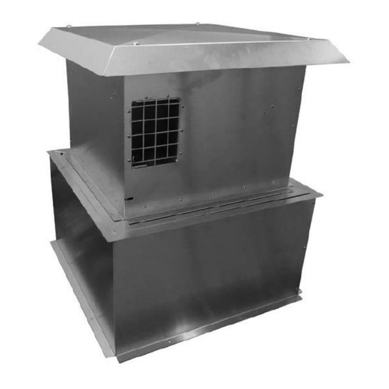
AA-11-04100 – Vertical Power Vent Kit: Vent runs up to 80 feet in length.
This component kit is to be with all Power Vent Kits
AA-11-05379 Power vent component kit for 4" x 6-5/8" vented fireplaces. The
instructions for this kit are at the end of this document.
ATTENTION: This installation must conform with local codes or, in the absence of local codes, with the National Fuel Gas
Code, ANSI Z223.1/NFPA 54, or the Natural Gas and Propane Installation Code, CSA B149.1.
All electrical installations should be performed by a qualified electrician to the Canadian and U.S. National Electrical
Codes (CSA C22.1 for Canada), (ANSI/NFPA 70 for the U.S.) and/or local electrical codes.
Tools
-
Phillips Head Screw Drive
-
Allen Wrenches
¼" Hex Driver.
-
-
Wire Stripper
-
Caulk Gun
Components – NOT INCLUDED WITH THE POWER VENT.
-
14/2 SOLID COPPER WIRE
The power vent kit must be wired to the fireplace using 14/2 solid copper wire. Required wire
length will depend on vent run length.
-
Weather sealant. Used to seal around the power vent.
85-03-01138
VERTICALLY TERMINATED
REQUIRED TOOLS AND COMPONENTS
Advertisement
Table of Contents

Subscribe to Our Youtube Channel
Related Manuals for Mendota AA-11-04100

Summary of Contents for Mendota AA-11-04100
-
Page 1: Required Tools And Components
NOTE: This kit must be installed by a qualified installer. These instructions are to be used in conjunction with the fireplace installation manual to insure proper installation. AA-11-04100 – Vertical Power Vent Kit: Vent runs up to 80 feet in length. This component kit is to be with all Power Vent Kits AA-11-05379 Power vent component kit for 4”... -
Page 2: Table Of Contents
Table of Contents REQUIRED TOOLS AND COMPONENTS ..........................1 Tools ....................................1 Components – NOT INCLUDED WITH THE POWER VENT....................1 POWER VENT KIT SERVICE PARTS ........................... 3 POWER VENT ..................................3 RISER ....................................4 DIMENSIONS..................................5 POWER VENT ..................................5 RISER .................................... -
Page 3: Power Vent Kit Service Parts
POWER VENT KIT SERVICE PARTS POWER VENT 80001234 80001235 80000554 80001236 BLOWER, POWER VENT 7-110 80001513 Page 3 of 24 85-03-01131... -
Page 4: Riser
RISER 80002101 RISER ASSEMBLY Page 4 of 24 85-03-01131... -
Page 5: Dimensions
DIMENSIONS POWER VENT Page 5 of 24 85-03-01131... -
Page 6: Riser
RISER Page 6 of 24 85-03-01131... -
Page 7: Venting Configurations
VENTING CONFIGURATIONS VENT PIPE Consult fireplace manual for approved vent pipe size and type. For all installations rigid, coaxial vent pipe is required. VENT RUN CHART ATTENTION: Vent pipe clearances to combustible material must be maintained to 3” above vent pipe and 1” on sides and bottom. -
Page 8: Riser
Minimum clearances to the vent terminal must be maintained as shown below. Measure clearances to the nearest edge of termination hood. NOTE: Local codes or regulations may require different clearances. NOTE: For flat roof installations, check local codes for elevated platform dimensional requirements. RISER A site fabricated riser or standoff must be built to elevate this power vent from any surface where water or snow could accumulate at the power vents base if not using supplied riser. - Page 9 Use weather sealant between the power vent and upper riser plate and the riser as necessary to prevent moisture from entering the power vent unit and building. Flash according to local codes. When attaching venting to the power vent insure that the vent tube overlaps the power vent tubing at least 1 ½” so that the vent can be secured with screws.
- Page 10 Page 10 of 24 85-03-01131...
-
Page 11: Wiring The Power Vent
WIRING THE POWER VENT The fireplace will have a junction box with two strain relief clamps. See the installation manual included with the fireplace for the location of the junction box. To connect the power vent to the fireplace, follow these steps. Remove the junction box cover plate from the side of the fireplace. - Page 12 At the other end, the power vent wire must be wired to the power vent blower housing. The power vent has an electrical connector block mounted internally. The wiring must be connected to this block. Remove the 4 hex screws holding the top cover in place and remove the cover. 9.
- Page 13 10. Run the electrical supply wire from the fireplace up through the bottom of the power vent and to the connector block inside the power vent assembly. Connect wires as shown and tighten the strain relief. Insure that the switch located beside the terminal block is toggled to high “HI”.
- Page 14 POWER VENT KIT INSTALLATION INSTRUCTIONS AA-11-05379 Power vent component kit for 4” x 6-5/8” vented fireplaces. Tools Needed - Large Flat Blade Screwdriver - Wire Cutters CONTROL MODULE PREPERATION The board will need to be opened to remove a component inside for the power vent to be operational. This can be done with the board still in the fireplace or it can be removed from the fireplace for easier access.
- Page 15 2. Locate the pin cover circled in the top photo. Grab it with your fingers and pull it straight up to remove it. You may discard this piece. Page 15 of 24 85-03-01131...
- Page 16 3. Place the top cover back onto the control module, make sure it is oriented properly, press lightly on the top cover till you hear a clicking sound engaging the retaining clips. 4. Re-install the control module back into the fireplace if it was removed. Page 16 of 24 85-03-01131...
- Page 17 PRESSURE SWITCH PREPARATION To begin preparation on the pressure switch you will first need to find the pressure switch, silicone hose, and power vent harness. The pressure switch and silicone hose are in the same box as these instructions. The power vent harness is the yellow harness with red quick connect connectors in the fireplace manual box.
- Page 18 2. Locate the end of the power vent wire harness with two female connectors. Connect this end of the power vent wire to the two silver terminals on the pressure switch marked “NO” and “COM”. These can be connected in either order it does not make a difference. Take the silicone hose and attach it to the hose barb on the pressure switch marked “L”.
- Page 19 The pressure switch will be installed in the fireplace near the control module. The pressure switch must be installed vertically. The photos in the instructions show the pressure switch being placed in a ML series fireplace. For all fireplaces the presser switch can be placed next to the control module in a similar way.
- Page 20 (ML-Series fireplaces) Route the silicone hose through the rear cutout of the fireplace. The cutout is located near the center of the fireplace at the bottom on the backside. The silicone hose can be routed from this hole to the pressure switch. (FV-Series fireplaces) Route the silicone hose through the cut out in the access panel where the gas line is connected.
- Page 21 WIRE HARNESS PREPARATION The wire harness needs to be modified for the power vent to be operational. You will need the wire cutters to remove a wire from the harness. The harness that needs to be modified will come already installed into the fireplace.
- Page 22 FIREPLACE PREPARATION Use Kit AA-11-05379 for the following steps. Note: For the following units DXV35DT4, FV34, FV34 ARCH, FV34 DÉCOR. Start with the 4 x 6 vent adapter with the pressure plate. Install the 5/8-4 x 6 reducer. 2. Attach the 4 x 6 vent adapter with pressure plate to the reducer in item one. Note: the height of the reducer and adapter attached is 11 ½”.
- Page 23 3. Install the 4 x 6- 5/8 increaser to the power vent. Page 23 of 24 85-03-01131...
- Page 24 REMOVE CPI FUNCTION FROM THE REMOTE. Remove the batteries from the remote. Then install the batteries while holding the power and mode buttons. This will bring up a display that will let you select or clear the functions on the remote. Keep the power button held down and use the mode button to toggle between functions.
Need help?
Do you have a question about the AA-11-04100 and is the answer not in the manual?
Questions and answers