ASROCK 770 EXTREME3 User Manual
Hide thumbs
Also See for 770 EXTREME3:
- Installation manual (193 pages) ,
- Specifications (6 pages) ,
- Manual (3 pages)

Related Manuals for ASROCK 770 EXTREME3


Summary of Contents for ASROCK 770 EXTREME3
-
Page 1: User Manual
770 Extreme3 User Manual Version 1.0 Published February 2010 Copyright©2010 ASRock INC. All rights reserved. 1 1 1 1 1... - Page 2 (including damages for loss of profits, loss of business, loss of data, interruption of business and the like), even if ASRock has been advised of the possibility of such damages arising from any defect or error in the manual or product.
-
Page 3: Table Of Contents
Installation ................. 25 Serial ATA3 (SATA3) Hard Disks Installation ......25 2.10 Hot Plug and Hot Swap Functions for SATA / SATAII HDDs ..26 2.11 Hot Plug and Hot Swap Functions for SATA3 HDDs ....26 2.12 SATA / SATAII HDD Hot Plug Feature and Operation Guide ..27 2.13 Driver Installation Guide ............ - Page 4 Hardware Health Event Monitoring Screen ......52 Boot Screen ................53 3.6.1 Boot Settings Configuration ........... 53 Security Screen ................ 54 Exit Screen ................55 4 . 4 . 4 . 4 . 4 . Software Support Software Support Software Support Software Support ......................
-
Page 5: Introduction Introduction
ASRock’s commitment to quality and endurance. In this manual, chapter 1 and 2 contain introduction of the motherboard and step-by-step guide to the hardware installation. Chapter 3 and 4 contain the configuration guide to BIOS setup and information of the Support CD. -
Page 6: Specifications
Conductive Polymer Capacitors) - Support for Socket AM3 processors: AMD Phenom II X4 / X3 / X2 (except 920 / 940) / Athlon II X4 / X3 / X2 / Sempron processors - Supports CPU up to 140W - Supports AMD OverDrive... - Page 7 - 2 x SATA3 6.0Gb/s connectors by Marvell SE9123/9120, support NCQ, AHCI and “Hot Plug” functions USB 3.0 - 1 x USB 3.0 port by Fresco FL1000G, support USB 3.0 up to 5Gb/s Connector - 4 x SATAII 3.0Gb/s connectors, support RAID (RAID 0, RAID 1, RAID 10 and JBOD), NCQ, AHCI and “Hot Plug”...
- Page 8 Overclocking may affect your system stability, or even cause damage to the components and devices of your system. It should be done at your own risk and expense. We are not responsible for possible damage caused by overclocking.
- Page 9 USB flash drive or hard drive must use FAT32/16/12 file system. 10. The software name itself – OC DNA literally tells you what it is capable of. OC DNA, an exclusive utility developed by ASRock, provides a conve- nient way for the user to record the OC settings and share with others.
-
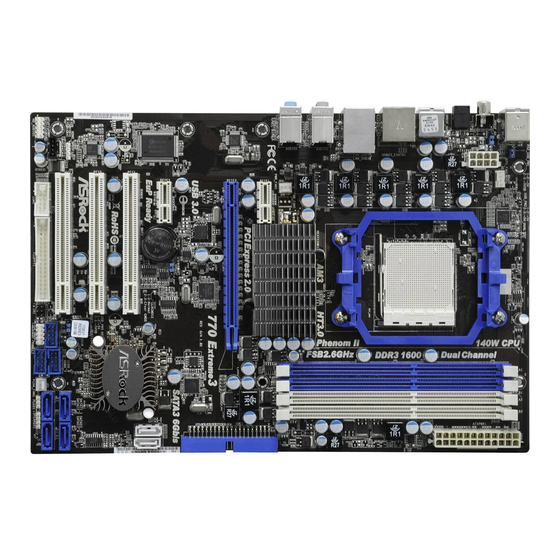
Page 10: Motherboard Layout
SATA3 Connector (SATA3_1, White) (HDMI_SPDIF1, White) Southbridge Controller PCI Slots (PCI1- 3) USB_PW3 Jumper PCI Express 2.0 x1 Slot (PCIE3; White) SATAII Connector (SATAII_1, Blue) Clear CMOS Jumper (CLRCMOS1) SATAII Connector (SATAII_3, Blue) PCI Express 2.0 x16 Slot (PCIE2; Blue) SATAII Connector (SATAII_4, Blue) PCI Express 2.0 x1 Slot (PCIE1;... -
Page 11: I/O Panel
Coaxial SPDIF Out Port ** 8 Front Speaker (Lime) PS/2 Keyboard Port (Purple) * There are two LED next to the LAN port. Please refer to the table below for the LAN port LED indications. LAN Port LED Indications ACT/LINK... -
Page 12: Installation
Installation Installation Installation This is an ATX form factor (12.0-in x 8.2-in, 30.5 cm x 20.8 cm) motherboard. Before you install the motherboard, study the configuration of your chassis to en- sure that the motherboard fits into it. Pre-installation Precautions... -
Page 13: Cpu Installation
Step 4. When the CPU is in place, press it firmly on the socket while you push down the socket lever to secure the CPU. The lever clicks on the side tab to indicate that it is locked. -
Page 14: Installation Of Memory Modules (Dimm)
(the same brand, speed, size and chip-type) DDR3 DIMM pair in the slots of the same color. In other words, you have to install identical DDR3 DIMM pair in Dual Channel A (DDR3_A1 and DDR3_B1; Blue slots;... - Page 15 DIMMs or the system components. Step 1. Unlock a DIMM slot by pressing the retaining clips outward. Step 2. Align a DIMM on the slot such that the notch on the DIMM matches the break on the slot. notch break...
-
Page 16: Expansion Slots (Pci And Pci Express Slots)
2.4 Expansion Slots (PCI and PCI Express Slots) 2.4 Expansion Slots (PCI and PCI Express Slots) There are 3 PCI slots and 3 PCI Express slots on this motherboard. PCI Slots: PCI slots are used to install expansion cards that have the 32-bit PCI interface. PCIE Slots: PCIE1 / PCIE3 (PCIE x1 slot;... -
Page 17: Jumpers Setup
CLRCMOS1 for 5 seconds. However, please do not clear the CMOS right after you update the BIOS. If you need to clear the CMOS when you just finish updating the BIOS, you must boot up the system first, and then shut it down... -
Page 18: Onboard Headers And Connectors
(33-pin FLOPPY1) FLOPPY1 Pin1 (see p.10 No. 27) the red-striped side to Pin1 Note: Make sure the red-striped side of the cable is plugged into Pin1 side of the connector. Primary IDE connector (Blue) (39-pin IDE1, see p.10 No. 9) IDE1... - Page 19 USB 2.0 Headers Besides five default USB 2.0 USB_PWR ports on the I/O panel, there are P-11 (9-pin USB10_11) P+11 three USB 2.0 headers on this DUMMY (see p.10 No. 23) motherboard.
- Page 20 HDA to function correctly. Please follow the instruction in our manual and chassis manual to install your system. 2. If you use AC’97 audio panel, please install it to the front panel audio header as below: A.
- Page 21 Though this motherboard provides 4-Pin CPU fan (Quiet Fan) support, the 3-Pin CPU fan still can work successfully even without the fan speed control function. If you plan to connect the 3-Pin CPU fan to the CPU fan connector on this motherboard, please connect it to Pin 1-3.
- Page 22 Though this motherboard provides 24-pin ATX power connector, it can still work if you adopt a traditional 20-pin ATX power supply. To use the 20-pin ATX power supply, please plug your power supply along with Pin 1 and Pin 13.
- Page 23 HDMI_SPDIF Cable Please connect the black end (A) of HDMI_SPDIF cable to the (Optional) HDMI_SPDIF header on the motherboard. Then connect the white end (B or C) of HDMI_SPDIF cable to the HDMI_SPDIF connector of HDMI VGA card. A. black end B.
-
Page 24: Hdmi_Spdif Header Connection Guide
HDMI (High-Definition Multi-media Interface) is an all-digital audio/video specification, which provides an interface between any compatible digital audio/video source, such as a set-top box, DVD player, A/V receiver and a compatible digital audio or video monitor, such as a digital television (DTV). A complete HDMI system requires a HDMI VGA card and a HDMI ready motherboard with a HDMI_SPDIF header. -
Page 25: Installation
STEP 4: Connect the other end of the SATA data cable to the SATA / SATAII hard disk. If you plan to use RAID 0 or RAID 1 function, you need to install at least 2 SATA / SATAII hard disks. If you plan to use RAID 10 function, you need to install at least 4 SATA / SATAII hard disks. -
Page 26: Hot Plug And Hot Swap Functions For Sata / Sataii Hdds
SATA / SATAII HDD. What is Hot Swap Function? If SATA / SATAII HDDs are built as RAID 1 then it is called “Hot Swap” for the action to insert and remove the SATA / SATAII HDDs while the system is still power-on and in working condition. -
Page 27: Sata / Sataii Hdd Hot Plug Feature And Operation Guide
1. Below operation procedure is designed only for our motherboard, which supports SATA / SATAII / SATA3 HDD Hot Plug. * The SATA / SATAII / SATA3 Hot Plug feature might not be supported by the chipset because of its limitation, the SATA / SATAII / SATA3 Hot Plug support information of our motherboard is indicated in the product spec on our website: www.asrock.com... - Page 28 SATA / SATAII / SATA3 HDD damage and data loss. Step 1 Unplug SATA data cable from SATA / SATAII / SATA3 HDD side. Unplug SATA 15-pin power cable connector (Black) from SATA / SATAII / SATA3 HDD side. Step 2...
-
Page 29: Driver Installation Guide
/ Vista 64-bit / XP / XP 64-bit on ® a RAID disk composed of 2 or more SATA / SATAII HDDs with RAID functions, please follow below procedures according to the OS you install. 2.14.1 Installing Windows 2.14.1 Installing Windows... -
Page 30: Installing Windows
64-bit OS on your system. When you see “Where do you want to install Windows?” page, please insert the ASRock Support CD into your optical drive, and click the “Load Driver” button on the left on the bottom to load the AMD RAID... -
Page 31: Installing Windows
(create, convert, delete, or rebuild) RAID functions on SATA / SATAII HDDs, you still need to set up “SATA Operation Mode” to [RAID] in BIOS first. Then, please set the RAID configuration by using the Windows RAID installation guide in the following path in the Support CD: .. -
Page 32: Without Raid Functions
SATA / SATAII driver diskette containing the AMD AHCI driver. After reading the floppy disk, the driver will be presented. Select the driver to install according to the OS you install. (Select “AMD AHCI Compatible RAID Controller-x86 platform” for Windows XP, or “AMD AHCI Compatible RAID Controller-x64 platform”... -
Page 33: Untied Overclocking Technology
Untied Overclocking function, please enter “Overclock Mode” option of BIOS setup to set the selection from [Auto] to [CPU, PCIE, Async.]. Therefore, CPU FSB is untied during overclocking, but PCI / PCIE buses are in the fixed mode so that FSB can operate under a more stable overclocking environment. -
Page 34: Bios S
This section explains how to use the BIOS SETUP UTILITY to configure your system. The SPI Memory on the motherboard stores the BIOS SETUP UTILITY. You may run the BIOS SETUP UTILITY when you start up the computer. Please press <F2> or <Del>... -
Page 35: Navigation Keys
To jump to the Exit Screen or exit the current screen <ESC> Main Screen Main Screen Main Screen Main Screen Main Screen When you enter the BIOS SETUP UTILITY, the Main screen will appear and display the system overview. BIOS SETUP UTILITY OC Tweaker Advanced H/W Monitor Boot... -
Page 36: Oc Tweaker Screen
You can use this option to load the optiomized CPU overclocking setting. Configuration options: [Press Enter], [Default], [5% (2310MHz)] to [50% (3300MHz)]. Please note that overclocking may cause damage to your CPU and motherboard. It should be done at your own risk and expense. CPU Configuration Overclock Mode Use this to select Overclock Mode. - Page 37 It will display Processor Maximum Voltage for reference. Multiplier/Voltage Change This item is set to [Auto] by default. If it is set to [Manual], you may adjust the value of Processor Frequency and Processor Voltage. However, it is recommended to keep the default value for system stability.
- Page 38 [25%], [37.5%], [50%], [62.5%], [75%] and [87.5%]. The default value is [Auto]. Memory Configuration Memory Clock This item can be set by the code using [Auto]. You can set one of the standard values as listed: [400MHz DDR3_800], [533MHz DDR3_1066], [667MHz DDR3_1333] and [800MHz DDR3_1600]. DRAM Voltage Use this to select DRAM voltage.
- Page 39 Bank Interleaving Interleaving allows memory accesses to be spread out over banks on the same node, or accross nodes, decreasing access contention. Channel Interleaving It allows you to enable Channel Memory Interleaving. Configuration options: [Disabled], [Address bits 6], [Address bits 12], [Address bits 6], [HASH 1] and [HASH 2].
- Page 40 Use this to adjust TRFC1 values. Configuration options: [Auto], [90ns], [110ns], [160ns], [300ns] and [350ns]. The default value is [Auto]. MA Timing Use this to adjust values for MA timing. Configuration options: [Auto], [2T], [1T]. The default value is [Auto]. CHA ADDR/CMD Delay Use this to adjust values for CHA ADDR/CMD Delay feature.
- Page 41 CHA Processor ODT Use this to adjust values for CHA Processor ODT. Configuration options: [Auto], [240 ohms], [120 ohms] and [60 ohms]. The default value is [Auto]. CHB CKE Drive Use this to adjust values for CHB CKE Drive. Configuration options: [Auto], [1.00x], [1.25x], [1.50x] and [2.00x].
- Page 42 CHB Processor ODT Use this to adjust values for CHB Processor ODT. Configuration options: [Auto], [240 ohms], [120 ohms] and [60 ohms]. The default value is [Auto]. Would you like to save current setting user defaults? In this option, you are allowed to load and save three user defaults...
-
Page 43: Advanced Screen
. Just launch ® this tool and save the new BIOS file to your USB flash drive, floppy disk or hard drive, then you can update your BIOS only in a few clicks without preparing an additional floppy diskette or other complicated flash utility. -
Page 44: Cpu Configuration
® please set this item to [Enabled]. Please note that enabling this function may reduce CPU voltage and memory frequency, and lead to system stability or compatibility issue with some memory modules or power supplies. Please set this item to [Disable] if above issue occurs. -
Page 45: Chipset Configuration
Primary Graphics Adapter This item will switch the PCI Bus scanning order while searching for video card. It allows you to select the type of Primary VGA in case of multiple video controllers. The default value of this feature is [PCI]. Configuration... -
Page 46: Acpi Configuration
Use this item to enable or disable Ring-In signals to turn on the system from the power-soft-off mode. PCI Devices Power On Use this item to enable or disable PCI devices to turn on the system from the power-soft-off mode. PS/2 Keyboard Power On Use this item to enable or disable PS/2 keyboard to turn on the system from the power-soft-off mode. -
Page 47: Storage Configuration
SATA Operation Mode Use this item to adjust SATA Operation Mode. The default value of this option is [IDE]. If you want to operate RAID function on SATA / SATAII HDDs, please select [RAID]. Configuration options: [AHCI], [RAID] and [IDE]. - Page 48 [ARMD]: This is used for IDE ARMD (ATAPI Removable Media Device), such as MO. LBA/Large Mode Use this item to select the LBA/Large mode for a hard disk > 512 MB under DOS and Windows; for Netware and UNIX user, select [Disabled] to disable the LBA/Large mode.
-
Page 49: Pcipnp Configuration
Setting wrong values in this section may cause the system to malfunction. PCI Latency Timer The default value is 32. It is recommended to keep the default value unless the installed PCI expansion cards’ specifications require other settings. PCI IDE BusMaster... -
Page 50: Floppy Configuration
Use this item to enable or disable floppy drive controller. Serial Port Address Use this item to set the address for the onboard serial port or disable it. Configuration options: [Disabled], [3F8 / IRQ4], [2F8 / IRQ3], [3E8 / IRQ4], [2E8 / IRQ3]. -
Page 51: Usb Configuration
Use this item to enable or disable the USB 2.0 support. Legacy USB Support Use this option to select legacy support for USB devices. There are four configuration options: [Enabled], [Auto], [Disabled] and [BIOS Setup Only]. The default value is [Enabled]. Please refer to below descriptions for the details of these four options: [Enabled] - Enables support for legacy USB. -
Page 52: Hardware Health Event Monitoring Screen
Hardware Health Event Monitoring Screen Hardware Health Event Monitoring Screen In this section, it allows you to monitor the status of the hardware on your system, including the parameters of the CPU temperature, motherboard temperature, CPU fan speed, chassis fan speed, and the critical voltage. -
Page 53: Boot Screen
3 . 6 3 . 6 Boot Screen Boot Screen In this section, it will display the available devices on your system for you to config- ure the boot settings and the boot priority. BIOS SETUP UTILITY Main OC Tweaker... -
Page 54: Security Screen
Boot From Onboard LAN Use this item to enable or disable the Boot From Onboard LAN feature. Boot Up Num-Lock If this item is set to [On], it will automatically activate the Numeric Lock function after boot-up. 3 . 7 3 . -
Page 55: Exit Screen
When you select this option, it will pop-out the following message, “Dis- card changes?” Select [OK] to discard all changes. Load BIOS Defaults Load BIOS default values for all the setup questions. F9 key can be used for this operation. Load Performance Setup Default (IDE/SATA) This performance setup default may not be compatible with all system configurations. -
Page 56: Software Support Software Support
4.2.1 Running The Support CD 4.2.1 Running The Support CD To begin using the support CD, insert the CD into your CD-ROM drive. The CD automatically displays the Main Menu if “AUTORUN” is enabled in your computer. If the Main Menu did not appear automatically, locate and double click on the file “ASSETUP.EXE”...
Need help?
Do you have a question about the 770 EXTREME3 and is the answer not in the manual?
Questions and answers