Table of Contents
Advertisement
OWNER'S MANUAL
MANUEL D'UTILISATION
BEDIENUNGSANLEITUNG
MANUALE PER IL PROPRIETARIO
EIERHÅNDBOK
INSTRUKTIONSBOK
OMISTAJAN KÄSIKIRJA
Read this manual carefully before operating this machine.
Il convient de lire attentivement ce manuel avant la première utilisation de la machine.
Bitte lesen Sie diese Bedienungsanleitung sorgfältig durch, bevor Sie die Maschine in Betrieb nehmen.
Leggere attentamente questo manuale prima di utilizzare questa macchina.
Les denne håndboken nøye før du tar maskinen i bruk.
Läs den här instruktionsboken noga innan maskinen används.
Lue tämä käsikirja huolellisesti ennen koneen käyttöä.
E
F
D
I
N
S
SF
YT1070
7RW-28199-U5
Advertisement
Table of Contents

Related Manuals for Yamaha YT1070


Summary of Contents for Yamaha YT1070
- Page 1 Bitte lesen Sie diese Bedienungsanleitung sorgfältig durch, bevor Sie die Maschine in Betrieb nehmen. Leggere attentamente questo manuale prima di utilizzare questa macchina. Les denne håndboken nøye før du tar maskinen i bruk. Läs den här instruktionsboken noga innan maskinen används. Lue tämä käsikirja huolellisesti ennen koneen käyttöä. YT1070 7RW-28199-U5...
- Page 3 OWNER’S MANUAL Read this manual carefully before operating this machine. YT1070 7RW-28199-U5-E0...
- Page 4 Read this manual carefully before operating this machine. This manual should stay with this machine if it is sold.
- Page 5 * Take care of this manual. Please attach this manual to the product when it is lent or transferred to an- other person. * When depositing the product, batteries, oil or other components, consult a Yamaha dealer for guide- lines on protecting the environment.
-
Page 6: Table Of Contents
CONTENTS PRODUCT SERIAL NUMBER LABEL ..... 1 STARTING THE ENGINE SAFETY INFORMATION ........2 (FOR ELECTRIC START) ......24 LOCATION OF IMPORTANT LABELS ..... 6 STOPPING THE ENGINE ......26 SYMBOL MEANING ........8 MOVING THE SNOWBLOWER ....27 DESCRIPTION ..........9 CLEARING SNOW ........ -
Page 7: Product Serial Number Label
PRODUCT SERIAL NUMBER LABEL Both the product name and the product serial Product name: number are required when making inquiries and reordering of parts. Check the product serial number label, and fill Product serial the product name and the serial number columns number: at right. -
Page 8: Safety Information
SAFETY INFORMATION Read and understand this owner’s manual and Never operate the Snowblower when you are labels attached to the Snowblower completely tired or under the influence of alcohol or drugs. before operating the Snowblower. Wear non-slip footwear, warm clothing and 1. - Page 9 SAFETY INFORMATION Do not start the engine with the guard or cover Gasoline is a highly flammable and easily ignit- removed. able fuel. Always turn off the engine and avoid open flame while filling the fuel tank. Check for foreign objects in rotating parts such as the auger and impeller or in the chute before Remove wooden blocks, cans, hoses, wires, operating.
- Page 10 SAFETY INFORMATION Do not allow anyone except the operator of the Do not fix the auger clutch lever or drive clutch Snowblower near the place you wish to clear lever intentionally as this will prevent the safety snow from. device to operate. Do not look in the rotating parts such as the au- Do not blow snow across the face of a slope.
- Page 11 Do not use the Snowblower for purposes other ticed coming from the Snowblower, stop the than clearing snow. engine and ask a Yamaha dealer to check and/or perform maintenance. To dislodge snow from the chute, stop the en- gine, and use the clean-out tool.
-
Page 12: Location Of Important Labels
LOCATION OF IMPORTANT LABELS To use the product safely, read the labels affixed to the machine, and use according to the instructions on the labels. If these important labels are damaged or missing, contact a Yamaha dealer for replacements. – 6 –... - Page 13 LOCATION OF IMPORTANT LABELS 7RV-51781-10 7RV-2415E-10 7RV-51782-10 – 7 –...
-
Page 14: Symbol Meaning
LOCATION OF IMPORTANT LABELS SYMBOL MEANING Please understand the following symbols before operating this machine. The Safety Alert Symbol means ATTENTION! BECOME ALERT! YOUR SAFETY IS INVOLVED! Read the manual before operation. 9 Gasoline is a highly flammable and easily ignitable fuel. 9 Always turn off the engine and avoid open flame while filling the fuel tank. -
Page 15: Description
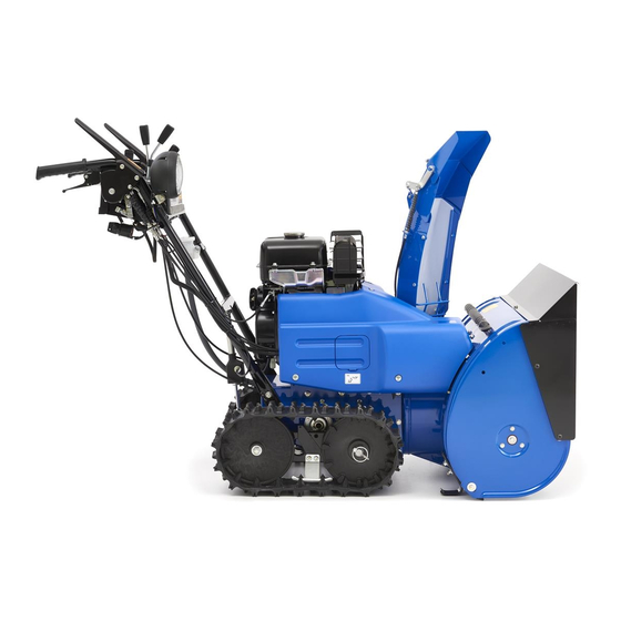
DESCRIPTION 1. Chute 8. Transmission (HST) oil reservoir 2. Muffler 9. Left side cover 3. Working light 10. Impeller 4. Fuel tank cap 11. Shear bolt guard 5. Fuse 12. Auger 6. Fuel gauge 13. Auger housing 7. Fuel tank 1. - Page 16 DESCRIPTION 1. Drive clutch lever 2. Shift lever 3. Chute deflector control lever 4. Chute direction control lever 5. Throttle/Choke lever 6. Auger clutch lever 7. Auger housing height control lever 8. Engine switch 1. Fuel tank cap 2. Fuel tank 3.
- Page 17 DESCRIPTION 1. Electric starter 3. Engine oil filler cap 2. Battery 4. Engine oil drain bolt 1. Spark plug cap/Spark plug 2. Carburetor – 11 –...
-
Page 18: Control Function
CONTROL FUNCTION ENGINE SWITCH RECOIL STARTER STOP START 1. “STOP 5 ” 1. Recoil starter handle 2. “ON 7 ” 3. “START 6 ” Used to start the engine. 4. Engine switch key Pull the recoil starter slowly until it is engaged, 5. -
Page 19: Shift Lever
CONTROL FUNCTION CHUTE DIRECTION CONTROL Throttle/Choke lever controls the choke and the engine speed. LEVER START 1: Lever position to start the engine. FAST :: Lever position to warm up the engine, start snow clearing or moving. SLOW Lever position to idle the engine. NOTICE When snow clearing or moving is started with the throttle/choke lever in the “SLOW... -
Page 20: Chute Deflector Control Lever
CONTROL FUNCTION CHUTE DEFLECTOR CONTROL Hold the drive clutch lever: The Snowblower travels. LEVER Release the drive clutch lever: The Snowblower stops traveling. AUGER CLUTCH LEVER 1. Chute deflector control lever 2. Pull 3. Push 4. Chute deflector 5. Upward 1. -
Page 21: Fuel Tank Cap
CONTROL FUNCTION To raise the auger housing: Indicates the fuel level in the fuel tank. Pull and hold the auger housing height control Refuel when the needle of fuel gauge is near “E” lever and push the handlebar down. Release the (Empty). -
Page 22: Skid
CONTROL FUNCTION Clearance between the Turn the fuel cock lever to this position to start auger end and the engine and when the engine is running. the road surface OFF: Factory set Turn the fuel cock lever to this position when the 5 mm (Standard position) Snowblower is not being used. -
Page 23: Shear Bolt Guard
Have a Yamaha dealer replace the part. 9 If you keep operating the Snowblower with the damper protruding from the shear bolt guard, the shear bolt could break. -
Page 24: Clean-Out Tool (Lodged Snow Remover)
CONTROL FUNCTION CLEAN-OUT TOOL (LODGED WORKING LIGHT SNOW REMOVER) 1. Working light 1. Chute When starting the engine, the working light 2. Clean-out tool (lodged snow remover) comes on automatically and illuminates the front of the Snowblower. 1. Impeller 2. Auger Used to remove snow lodged or attached to chute, auger and impeller. -
Page 25: Pre-Operation Check
9 If any abnormalities are discovered, car- 5.8 L ry out maintenance by yourself or have a Yamaha dealer perform it for you. CHECK BEFORE USE For safe and comfortable use of your Snowblow- er, always check the following items before use. -
Page 26: Checking The Engine Oil
PRE-OPERATION CHECK 9 Refill the fuel tank slowly. 9 Refill the fuel tank before it becomes empty. CHECKING THE ENGINE OIL Remove the engine oil filler cap, and make sure the engine oil is at the correct engine oil level. WARNING Position the Snowblower on a level surface. -
Page 27: Checking The Transmission (Hst) Oil
PRE-OPERATION CHECK CHECKING THE TRANSMISSION 3. Make sure that the engine oil is at the cor- rect engine oil level. (HST) OIL Check the transmission (HST) oil quantity before starting the engine and the transmission (HST) is cold. 1. Check the oil reservoir under the control panel. -
Page 28: Checking The Auger
2. Drive clutch lever ness or play by moving it left and right. If any looseness or play is found, consult a CHECKING THE CHUTE Yamaha dealer. OPERATION CHECKING THE STARTER After starting the engine, make sure that the MOTOR OPERATION chute direction control lever and the chute de- Turn the engine switch key to the “START 6”... -
Page 29: Operation
OPERATION STARTING THE ENGINE 2. Turn the fuel cock lever from the “OFF” posi- tion to the “ON” position. (FOR RECOIL START) WARNING Never operate the engine in a closed area. Exhaust fumes contain harmful chemicals such as carbon monoxide. Operating the en- gine in poor ventilated area or indoor could cause the carbon monoxide poisonous. -
Page 30: Starting The Engine
OPERATION 5. Pull the recoil starter slowly until it is en- 7. When the engine is warmed up, move the gaged, then pull it briskly. throttle/choke lever from the “FAST :” posi- tion to the “SLOW ” position. 1. Recoil starter handle 1. - Page 31 OPERATION 1. Auger clutch lever 1. Throttle/Choke lever 2. Drive clutch lever 2. “START 1 ” 3. “SLOW ” 2. Turn the fuel cock lever from the “OFF” posi- tion to the “ON” position. 4. Start the engine by turning the engine switch key to the “START 6”...
-
Page 32: Stopping The Engine
OPERATION STOPPING THE ENGINE 5. After starting the engine, leave the engine to warm up for a while, and then move the 1. Turn the engine switch key to the “STOP 5” throttle/choke lever from the “START 1” po- position. sition to the “FAST :”... -
Page 33: Moving The Snowblower
OPERATION MOVING THE SNOWBLOWER 3. Hold the drive clutch lever. 1. Use the auger housing height control lever to NOTICE raise the auger to the highest position. 9 Move the shift lever to the “N” (Neutral) position first, and then hold the drive clutch lever. -
Page 34: Clearing Snow
OPERATION CLEARING SNOW 4. Hold the auger clutch lever. The auger starts rotating. WARNING WARNING 9 Do not point the discharge chute toward After first ensuring the snow blowing direc- people, buildings or cars. tion is safe, then hold the auger clutch lever. 9 If any foreign objects have become lodged in the impeller, auger, or track, stop the engine immediately and remove them. - Page 35 OPERATION 9 Snow is blown more effectively when the Snowblower is driven slowly. 1. Drive clutch lever 1. Shift lever If the drive clutch lever is held while you are 2. “F” (Forward) holding the auger clutch lever, the auger clutch 3.
- Page 36 OPERATION Drive clutch lever and auger clutch lever Useful information for operation If the auger clutch lever is held once while you are holding the drive clutch lever, the auger clutch lever will become fixed. The Snowblower will carry out snow clearing even if the auger clutch lever is released. Hold the drive Release the auger Release the drive...
-
Page 37: Stopping The Snowblower
OPERATION STOPPING THE SNOWBLOWER 1. Release the auger clutch lever and drive clutch lever. 1. Auger clutch lever 1. Auger clutch lever 2. Drive clutch lever 2. Move the shift lever to the “N” (Neutral) posi- tion. 4. Release the auger clutch lever. 1. -
Page 38: Moving The Snowblower With The Engine Stopped
OPERATION 1. Remove the sprocket pin from the sprocket wheel by pulling on the ring. 2. Insert the sprocket pin into the hole of the wheel axle and then fold the ring of the sprocket pin. Remove the sprocket pin from the both side of the wheels. -
Page 39: Periodic Maintenance
WARNING If you are not familiar with maintenance work, have a Yamaha dealer do it for you. CHECK BEFORE USE The customer needs to perform the routine inspection (see page 19). If any problems are discovered dur- ing the inspection, contact a Yamaha dealer and request an inspection or maintenance. -
Page 40: Maintenance Chart
NOTICE Use only Yamaha specified genuine parts for replacement. Ask an authorized Yamaha dealer for further attention. Items marked with an asterisk should be performed by a Yamaha dealer as they require special tools, data and technical skills. Initial Every... - Page 41 PERIODIC MAINTENANCE Initial Every Pre- Item Routine operation Remarks check month months months 9 Oil level Transmission * 9 Oil leakage Ignition system 9 Checking the spark plug 9 Fluid level and specific Battery gravity 9 Electric starter working conditions 9 Engine starting conditions and abnormal noise 9 Measurement of rated...
-
Page 42: Changing The Engine Oil
9 As correct disposal of used oils is mandated by regulations (such as pollution prevention act), consult a Yamaha dealer for oil disposal guidelines. 1. Engine oil filler cap 9 For the first engine oil change, change the 2. -
Page 43: Refilling The Transmission (Hst) Oil
PERIODIC MAINTENANCE 2. Remove the oil reservoir cap and the dia- phragm. 1. Correct engine oil level Engine oil quantity: 1. Oil reservoir cap 1.0 L 2. Diaphragm Recommended engine oil: See page 21 3. Refill the transmission (HST) oil to an inter- mediate level between the maximum level mark and minimum level mark of the trans- mission (HST) oil reservoir. -
Page 44: Changing The Worm Case Oil
4. Left side cover CHANGING THE WORM CASE 3. Remove the spark plug cap. If necessary, have a Yamaha dealer change the worm case oil. For the first worm case oil change, change the worm case oil after 20 operating hours (that is, when you have refueled four times). -
Page 45: Cleaning The Fuel Strainer
5. Check the spark plug for any signs of burns. Burn marks on spark plugs are usually medium-to-light tan. If there are any black or white burn marks, consult a Yamaha dealer. 6. Remove deposits (carbon) from the spark plug electrode using a plug cleaner or a wire brush. -
Page 46: Adjusting The Skids
PERIODIC MAINTENANCE 3. Remove the ring nut, and then remove the 7. Turn the fuel cock lever to the “ON” position, fuel strainer cup, the gasket and the fuel and make sure that no fuel leaks out. strainer. ADJUSTING THE SKIDS WARNING Position the Snowblower on a level surface. -
Page 47: Replacing The Auger Shear Bolts
PERIODIC MAINTENANCE 3. Lift the auger housing, using the auger hous- Tightening torque: ing height control lever. Nut: 16 N·m (1.6 kgf·m) REPLACING THE AUGER SHEAR BOLTS WARNING 9 Do not look into or put your hands near the impeller or auger when they are rotat- ing. -
Page 48: Replacing The Impeller Shear Bolt
PERIODIC MAINTENANCE 3. Remove the locknuts, the shear bolts and 2. Be sure to use the clean-out tool (lodged the washers. snow remover) to remove snow and other obstacles from the auger housing. 1. Locknut 2. Shear bolt 3. Remove the locknut and shear bolt. 3. -
Page 49: Adjusting The Scraper
PERIODIC MAINTENANCE ADJUSTING THE SCRAPER 5. Be sure the scraper is horizontal, and then tighten the nuts and bolts to the specified torques. WARNING Position the Snowblower on a level surface. Tightening torque: Nut: 1. Stop the engine and remove the engine 9 N·m (0.9 kgf·m) switch key. -
Page 50: Replacing The Sprocket Pin
PERIODIC MAINTENANCE REPLACING THE SPROCKET PIN 2. Loosen the wheel nut on both sides. If an excessive load is applied to the driving sys- tem, for example, when the Snowblower is stuck in a rut, the sprocket pin will be cut to protect the driving system. -
Page 51: Checking The Battery Fluid
5. Check the cap vent hole for clogging. If 0 KEEP THIS AND ALL BATTERIES OUT OF clogged, consult a Yamaha dealer. THE REACH OF CHILDREN. 6. Install the right side cover and collars to their original positions, and tighten the screws 2. - Page 52 2. Blown fuse 1. Screw 2. Control panel If the fuse immediately blows again, have a Yamaha dealer check the electrical system. 4. Replace the blown fuse with a new one. 5. Install the control panel to its original posi- Fuse capacity: tion, and tighten the screws.
-
Page 53: Lubricating Each Part
PERIODIC MAINTENANCE LUBRICATING EACH PART Lubricate each drive shaft (arrow portion) with grease or engine oil (SAE 5W-30) every month of opera- tion or after every 10 hours of each operation, whichever comes first. 9 Moving parts of chute deflector control lever 9 Shift lever moving parts 9 Chute assembly moving parts 9 Chute motor gears and ring gears... - Page 54 PERIODIC MAINTENANCE 7. Chute assembly moving parts 8. Chute motor gears and ring gears – 48 –...
-
Page 55: Storage
STORAGE To have your Snowblower checked or maintained before storage, consult a Yamaha dealer. If you conduct the checks and maintenance by yourself, handle the gasoline carefully and use the following procedure. WARNING Gasoline is a highly volatile and flammable fuel. - Page 56 STORAGE Prepare a suitable container to collect the ex- tracted gasoline. 5. Turn the fuel cock lever from the “ON” posi- tion to the “OFF” position. 1. Container If the ring nut is too tight, loosen it using a pliers or other tool.
-
Page 57: Long-Term
STORAGE 8. Turn the fuel cock lever from the “ON” posi- 10. After all remaining gasoline has been ex- tion to the “Carb Drain” position. Drain the tracted from the fuel tank, spray a rust inhibi- gasoline from the carburetor into the con- tor against the fuel tank walls. -
Page 58: Specifications
SPECIFICATIONS Model name YT1070 Overall length 1506 mm Overall height 1105 mm Overall width 745 mm Weight 141 kg Snow clearing width 715 mm Snow clearing height 510 mm Snow blowing system Dual-stage auger blower Chute rotation angle 220 °... - Page 59 NOISE AND VIBRATION Model name YT1070 Sound pressure level at operator’s ears 89 dB(A) (EN ISO11200: 1995) Uncertainty...
-
Page 60: Index
INDEX FUEL TANK CAP ......... 15 ADJUSTING THE SCRAPER ...... 43 ADJUSTING THE SKIDS......40 LOCATION OF IMPORTANT LABELS... 6 AUGER CLUTCH LEVER ......14 LUBRICATING EACH PART ......47 AUGER HOUSING HEIGHT CONTROL LEVER ........14 MAINTENANCE CHART ......34 MOVING THE SNOWBLOWER .... - Page 62 PRINTED IN JAPAN YAMAHA MOTOR CO., LTD. 2020.06-0.1×1 !
- Page 64 Original instructions Notice originale Originalbetriebsanleitung Istruzioni originali Opprinnelige instruksjoner Bruksanvisning i original Alkuperäiset ohjeet PRINTED IN JAPAN 2020.06-0.1×1 ! (E, F, G, H, N, M, L)
Need help?
Do you have a question about the YT1070 and is the answer not in the manual?
Questions and answers