
Related Manuals for Yamaha YS928J


Summary of Contents for Yamaha YS928J
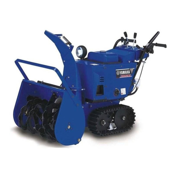
- Page 1 Snowblower Read this manual carefully before operating this machine. OWNER’S MANUAL YS928J 7VY-28199-70...
- Page 2 * Take care of this manual. Please attach this manual to the product when it is lent or trans- ferred to another person. * When depositing the product, batteries, oil or other components, consult your Yamaha dealer for guidelines on protecting the environment.
-
Page 3: Table Of Contents
CONTENTS PRODUCT SERIAL NUMBER LABEL..1 CHECKING THE ENGINE FOR SAFETY INFORMATION ......2 POOR STARTING OR ABNORMAL LOCATION OF IMPORTANT LABELS ..7 NOISE ..........29 DESCRIPTION.......... 9 CHECKING THE EXHAUST CONTROL FUNCTION ......14 SYSTEM .......... 29 ENGINE SWITCH ........ 14 CHECKING THE AUGER CLUTCH OIL LEVEL WARNING LIGHT ..... - Page 4 CONTENTS CHECKING THE BATTERY FLUID ..56 REPLACING THE FUSE ..... 57 LUBRICATING EACH PART ....58 STORAGE..........59 SHORT-TERM........59 LONG-TERM ........63 SPECIFICATIONS ........64 INDEX ............. 65...
-
Page 5: Product Serial Number Label
PRODUCT SERIAL NUMBER LABEL Both the product name and the product Product name: serial number are required when making inquiries and reordering of parts. Check the product serial number label, and Product serial fill the product name and the serial number number: columns at right. -
Page 6: Safety Information
SAFETY INFORMATION Read and understand this owner’s manual Never operate the Snowblower when you and labels attached to the Snowblower are tired or under the influence of alcohol or completely before operating the Snow- drugs. blower. 1. Owner’s manual Wear non-slip footwear, warm clothing and Be sure to perform the pre-operation gloves when operating the Snowblower. - Page 7 SAFETY INFORMATION Do not start the engine with the guard or Never start the engine indoors except when cover removed. you are moving the Snowblower. Exhaust fumes contain harmful chemicals such as carbon monoxide. Open the door and adequately ventilate the building even when you are moving the Snowblower.
- Page 8 SAFETY INFORMATION Remove wooden blocks, cans, hoses, Do not look in the rotating parts such as the wires, ropes and all other foreign objects auger and impeller or in the chute or put from the location you wish to clear snow your face, arms or legs near such parts.
- Page 9 “N” (Neutral). If abnormal vibrations, noises or odors are noticed coming from the Snowblower, stop 1. Auger the engine and ask your Yamaha dealer to 2. Shift lever check and/or perform maintenance. The muffler (exhaust pipe) will still be hot immediately after the engine has stopped.
- Page 10 SAFETY INFORMATION Do not use the Snowblower for purposes other than clearing snow. To dislodge snow from the chute, stop the engine, and use the clean-out tool. 1. Chute To attach a cover or similar device to the Snowblower, wait until the engine and muf- fler have completely cooled down.
-
Page 11: Location Of Important Labels
LOCATION OF IMPORTANT LABELS To use the product safely, read the labels affixed to the machine, and use according to the instructions on the labels. If these important labels are damaged or missing, contact your Yamaha dealer for replace- ments. – 7 –... - Page 12 LOCATION OF IMPORTANT LABELS 7VY-2179R-00 – 8 –...
-
Page 13: Description
DESCRIPTION 1. Chute 2. Battery cover/Battery 3. Transmission (HST) oil reservoir 4. Muffler 5. Fuel cock 6. Left side cover 7. Track 8. Auger 9. Impeller 10. Auger housing 11. Clean-out tool (lodged snow remover) 12. Side marker (snow slicer) –... - Page 14 DESCRIPTION 1. Working light 2. Right side cover 3. Engine oil inspection cover 4. Scraper 5. Skid 6. Control panel 7. Handlebar – 10 –...
- Page 15 DESCRIPTION 1. Drive clutch lever 2. Auger clutch lever 3. Shift lever 4. Chute direction control lever 5. Chute deflector control lever 6. Throttle lever 7. Oil level warning light 8. Auger housing height control lever 9. Engine switch CARBURETOR 1.
- Page 16 DESCRIPTION 1. Fuse 2. Electric starter 3. Engine oil filler cap 4. Engine oil drain bolt – 12 –...
- Page 17 DESCRIPTION 1. Spark plug cap/Spark plug 2. Carburetor 3. Air filter 4. Fuel drain hose 5. Fuel strainer cup 6. Fuel cock lever – 13 –...
-
Page 18: Control Function
CONTROL FUNCTION ENGINE SWITCH Remove the engine switch key when you are not using the Snowblower. 1. “STOP ” 2. “ON ” 3. “START ” 4. Grip The engine switch controls the ignition and the starter motor system. STOP Position to stop the engine. The key can be inserted or removed. -
Page 19: Oil Level Warning Light
CONTROL FUNCTION OIL LEVEL WARNING LIGHT THROTTLE LEVER 1. Oil level warning light 1. Throttle lever 2. “FAST (START) ” The oil level warning light comes on when 3. “SLOW ” the engine oil level falls below the specified limit during operation. Controls the engine speed. -
Page 20: Shift Lever
CONTROL FUNCTION SHIFT LEVER CHUTE DIRECTION CONTROL LEVER 1. Shift lever 2. “F” (Forward) 1. Chute direction control lever 3. “N” (Neutral) 2. Right 4. “R” (Reverse) 3. Left 4. Chute Used to switch to forward or reverse move- 5. Clockwise ment, and to control traveling speed. -
Page 21: Chute Deflector Control Lever
CONTROL FUNCTION CHUTE DEFLECTOR If you use the chute direction control lever when the engine is not run- CONTROL LEVER ning, it may exhaust the battery. The chute movement speed does not increase even if you press the chute direc- tion control lever forcefully. -
Page 22: Drive Clutch Lever
CONTROL FUNCTION DRIVE CLUTCH LEVER AUGER CLUTCH LEVER 1. Drive clutch lever 1. Auger clutch lever Used to make the Snowblower travel. Used to rotate the auger. Hold the drive clutch lever: Pull the auger clutch lever: The Snowblower travels. The auger rotates. -
Page 23: Auger Housing Height Control Lever
CONTROL FUNCTION AUGER HOUSING HEIGHT FUEL TANK CAP CONTROL LEVER 1. Fuel tank cap 1. Auger housing height control lever Turn the fuel tank cap counterclockwise to remove. Used to adjust the height of the auger hous- ing. WARNING To raise the auger housing: After refueling, make sure the fuel tank Pull and hold the auger housing height con- cap is tightened securely. -
Page 24: Fuel Gauge
CONTROL FUNCTION FUEL GAUGE FUEL COCK CARBURETOR 1. Fuel gauge 1. Fuel cock lever 2. Needle 2. “RUN” 3. “E” (Empty) 3. “STOP” 4. Fuel cock Indicates the fuel level in the fuel tank. 5. “CARBURETOR DRAIN” Refuel when the needle of the fuel gauge is 6. -
Page 25: Fuses
CONTROL FUNCTION FUSES SKID 1. Fuse cover 1. Skid 2. Fuse 2. Auger end 3. Spare fuse 3. Road surface 4. Clearance The fuses are located behind the right side cover. Skid is used to determine a clearance between the auger end and the road sur- face. -
Page 26: Scraper
CONTROL FUNCTION SCRAPER SHEAR BOLT GUARD 1. Scraper 1. Shear bolt guard 2. Shear bolt The scraper is used to flatten the surface to clear snow. Adjust the clearance between If any foreign objects become lodged in the the road surface and the scraper end auger, or the auger hits a curb, the shear according to road surface conditions (see bolt guard will run idle to absorb the impact... -
Page 27: Clean-Out Tool (Lodged Snow Remover)
CONTROL FUNCTION CLEAN-OUT TOOL (LODGED • Wear gloves when using the clean- out tool (lodged snow remover). SNOW REMOVER) 1. Chute 2. Clean-out tool (lodged snow remover) 1. Impeller 2. Auger Used to remove snow lodged or attached to chute, impeller and auger. WARNING •... -
Page 28: Working Light
CONTROL FUNCTION WORKING LIGHT 1. Working light When starting the engine, the working light comes on automatically and illuminates the front of the Snowblower. Bulb: 12 V, 23 W – 24 –... -
Page 29: Pre-Operation Check
Conduct checks or maintenance after the engine and muffler have completely cooled down. • If any abnormalities are discovered, carry out maintenance by yourself or have a Yamaha dealer perform it for you. – 25 –... -
Page 30: Checking The Fuel Level
PRE-OPERATION CHECK CHECKING THE FUEL LEVEL electricity on their bodies may cause a spark. Check that the needle in the fuel gauge is • Only refuel outdoors. pointing to the “F” (Full) level. • Do not fill gasoline above the speci- If the fuel level is low, remove the fuel tank fied level (up to the base of the filler cap and refill the tank. -
Page 31: Checking The Engine Oil
PRE-OPERATION CHECK CHECKING THE ENGINE OIL Recommended brand: Remove the engine oil filler cap, and make YAMALUBE sure that the engine oil is at the correct Type: engine oil level. SAE 5W-30 1. Position the Snowblower on a level sur- Recommended engine oil grade: face. -
Page 32: Checking The Transmission (Hst) Oil
PRE-OPERATION CHECK CHECKING THE TRANSMIS- When the ambient temperature is low (below approx. -20 C) or before operating SION (HST) OIL the Snowblower, you may not be able to Check that the transmission (HST) oil is at see the level of transmission (HST) oil in the specified level. -
Page 33: Checking The Auger
Hold the handlebar and check it for any looseness or play by moving it left and right. If any looseness or play is found, consult 1. Auger clutch lever your Yamaha dealer. 2. Drive clutch lever CHECKING THE STARTER CHECKING THE CHUTE... -
Page 34: Operation
OPERATION STARTING THE ENGINE WARNING Never operate the engine in a closed area, otherwise it may cause uncon- sciousness and death within a short time. Operate the engine in a well-venti- lated area. 1. Turn the shift lever to the “N” (Neutral) CARBURETOR position, and make sure that both auger clutch lever and drive clutch lever... - Page 35 1. Throttle lever light comes on. 2. “FAST (START) ” If not, the bulb of the oil level warning 3. “SLOW ” light may have been burnt out. In this case, contact your Yamaha dealer for service. – 31 –...
-
Page 36: Stopping The Engine
OPERATION STOPPING THE ENGINE MOVING THE SNOWBLOWER 1. Turn the engine switch key to the 1. Use the auger housing height control “STOP ” position. lever to raise the auger to the highest position. 1. “STOP ” 2. Engine switch 1. - Page 37 OPERATION 1. Throttle lever 1. Drive clutch lever 2. “FAST (START) ” 3. “SLOW ” 4. Slowly move the shift lever from “N” (Neutral) position to forward or reverse. 3. Hold the drive clutch lever. NOTICE Operate the shift lever slowly. 1.
-
Page 38: Clearing Snow
OPERATION CLEARING SNOW WARNING • Do not point the discharge chute toward people, buildings or cars. • If any foreign objects have become lodged in the impeller, auger, or track, stop the engine immediately and remove them. Check the Snowblower for damage. If any damage is found, repair the Snowblower completely... - Page 39 OPERATION 1. Auger clutch lever 1. Shift lever 2. “N” (Neutral) If the auger clutch lever is pulled up fully 7. When releasing the drive clutch lever, while you are holding the drive clutch lever, the auger clutch lever automatically the auger clutch lever will become fixed to returns to its original position, the its pull-up position.
- Page 40 OPERATION Drive clutch lever and auger clutch lever Useful information for operation To move the Snowblower, hold the drive clutch lever. If the auger clutch lever is pulled back while the drive clutch lever is being held, the Snowblower will still travel and blow snow. Release the drive Hold the drive clutch Move the shift lever to...
-
Page 41: Stopping Clearing Snow
OPERATION STOPPING CLEARING SNOW 1. Release the drive clutch lever. The auger rotation stops, and the Snow- blower stops moving. 3. Release the drive clutch lever. Release the auger clutch lever at the same time. 1. Drive clutch lever 2. Move the shift lever to the “N” (Neutral) position. -
Page 42: Moving The Snowblower With The Engine Stopped
OPERATION MOVING THE SNOWBLOWER WITH THE ENGINE STOPPED Follow the step below to move the Snow- blower with the engine stopped. NOTICE • Do not start the engine. • Position the Snowblower on a level surface before beginning the follow- ing procedure. - Page 43 OPERATION 5. Remove the sprocket pins from the wheel axle and insert them into the hole of each wheel, and then fold the ring of the sprocket pin downward to lock it. NOTICE • Do not hammer the sprocket pins. •...
-
Page 44: Periodic Maintenance
WARNING If you are not familiar with maintenance work, have a Yamaha dealer do it for you. CHECK BEFORE USE The customer needs to perform the routine inspection (see page 25). If any problems are dis- covered during the inspection, contact your Yamaha dealer and request an inspection or maintenance. -
Page 45: Maintenance Chart
NOTICE Use only Yamaha specified genuine parts for replacement. Ask an authorized Yamaha dealer for further attention. Items marked with an asterisk should be performed by a Yamaha dealer as they require spe- cial tools, data and technical skills. Pre-... - Page 46 PERIODIC MAINTENANCE Pre- Initial Every opera- Item Routine Remarks tion month months months check • Oil level Transmission * • Oil leakage • Checking the spark Ignition system plug • Fluid level and specific Battery gravity • Electric starter working conditions •...
-
Page 47: Changing The Engine Oil
• As correct disposal of used oils is man- 2. Engine oil inspection cover dated by regulations (such as pollution 3. Bolt prevention act), consult your Yamaha 4. Screw dealer for oil disposal guidelines. • For the first engine oil change, change 5. -
Page 48: Refilling The Transmission (Hst) Oil
PERIODIC MAINTENANCE REFILLING THE TRANSMIS- Tightening torque: SION (HST) OIL Engine oil drain bolt: 30 Nm (3.0 m·kgf, 21 ft·lbf) WARNING 8. Refill new engine oil up to the brim of Position the Snowblower on a level sur- the oil filler hole. face. - Page 49 PERIODIC MAINTENANCE 1. Transmission (HST) oil reservoir 1. Alignment mark 2. Oil reservoir cap 2. Diaphragm 3. Maximum level mark “UPPER” 3. Oil reservoir cap 4. Minimum level mark “LOWER” NOTICE • Make sure that no foreign material such as dirt enters the oil reservoir during refilling.
-
Page 50: Changing The Worm Case Oil
PERIODIC MAINTENANCE CHANGING THE WORM CASE CHECKING AND CLEANING THE SPARK PLUG If necessary, have a Yamaha dealer change The spark plug is an important component the worm case oil. that can be checked relatively easily. As the effectiveness of the spark plug gradually... - Page 51 If there are any 18 Nm (1.8 m·kgf, 13 ft·lbf) black or white burn marks, consult your Yamaha dealer. 6. Remove deposits (carbon) from the If a torque wrench is not available when spark plug electrode using a plug installing a spark plug, a good estimate of cleaner or a wire brush.
-
Page 52: Cleaning The Fuel Strainer
PERIODIC MAINTENANCE CLEANING THE FUEL 9. Install the spark plug cap. 10. Install the left side cover by installing STRAINER the bolts. WARNING Tightening torque: Gasoline is a highly volatile and flamma- Left side cover bolt: ble fuel. When handling gasoline, be 10 Nm (1.0 m·kgf, 7.2 ft·lbf) sure to observe the following points. - Page 53 PERIODIC MAINTENANCE WARNING Be sure the ring nut is tightened securely. 8. Turn the fuel cock lever to the “RUN” position, and make sure that no fuel leaks out. 9. Install the left side cover by installing the bolts. Tightening torque: Left side cover bolt: 1.
-
Page 54: Adjusting The Skids
PERIODIC MAINTENANCE ADJUSTING THE SKIDS WARNING Position the Snowblower on a level sur- face. 1. Auger housing height control lever 2. Auger housing 3. Loosen the nuts of the skid. 1. Skid 2. Auger end 3. Road surface 4. Clearance Adjust the clearance between the auger end and the road surface correctly accord- ing to the road conditions. -
Page 55: Replacing The Shear Bolts
PERIODIC MAINTENANCE REPLACING THE SHEAR 5. Tighten the nuts of skid to the specified torque. BOLTS Tightening torque: WARNING Nut: • Do not look into or put your hands 16 Nm (1.6 m·kgf, 12 ft·lbf) near the impeller or auger when they are rotating. -
Page 56: Adjusting The Scraper
PERIODIC MAINTENANCE ADJUSTING THE SCRAPER 5. Install the lock nuts and then tighten them to the specified torque. WARNING NOTICE Position the Snowblower on a level sur- • Tighten the lock nuts to the speci- face. fied torque. Shear bolts may be damaged they loosely... -
Page 57: Checking And Adjusting The Track Tension
PERIODIC MAINTENANCE CHECKING AND ADJUSTING THE TRACK TENSION Make sure that the tension of the track is correct. If the tension of the track is not correct, the track may slip or it may fall off. Adjust the tension if necessary. WARNING Position the Snowblower on a level sur- face. - Page 58 PERIODIC MAINTENANCE 2. Loosen the wheel nut on both sides. Tightening torque: Locknut: 25 Nm (2.5 m·kgf, 18 ft·lbf) Wheel nut: 53 Nm (5.3 m·kgf, 38 ft·lbf) 1. Wheel nut 3. Loosen the locknut, and adjust the track slack by turning the adjusting bolt. 1.
-
Page 59: Replacing The Sprocket Pin
PERIODIC MAINTENANCE REPLACING THE SPROCKET If an excessive load is applied to the driving system, for example, when the Snowblower is stuck in a rut, the sprocket pin will be cut to protect the driving system. If the sprocket pin is broken, replace it immediately. -
Page 60: Checking The Battery Fluid
3. If the battery fluid is below the mini- mum level mark, add distilled water. 4. Check the cap vent hole for clogging. If clogged, consult your Yamaha dealer. Measure the specific gravity (must be 1.28 or more) periodically (every 6 months), and check the battery conditions. -
Page 61: Replacing The Fuse
2. Remove the right side cover by remov- ing bolts. 1. New fuse 2. Blown fuse If the fuse immediately blows again, have a Yamaha dealer check the electrical system. 1. Right side cover 2. Bolt 4. Install the right side cover by installing bolts. -
Page 62: Lubricating Each Part
PERIODIC MAINTENANCE LUBRICATING EACH PART Lubricate each drive shaft with grease or gasoline engine oil (SAE 5W-30) every month of operation or after every 10 hours of each operation, whichever comes first. • Moving parts of chute deflector control lever •... -
Page 63: Storage
STORAGE SHORT-TERM To have your Snowblower checked or main- tained before storage, consult your Yamaha If you need to store the Snowblower for dealer. more than 3 months, follow steps 1–18 to If you conduct the checks and maintenance make sure it is ready for the next use. - Page 64 STORAGE 1. “RUN” 1. Bolt 2. “STOP” 2. Fuel cock bracket 3. Fuel cock lever 7. Place a suitable container below the 5. Remove the left side cover by removing fuel cock to collect the drained gaso- the bolts. line. Remove the ring nut of the fuel cock, and then remove the fuel strainer cup.
- Page 65 STORAGE 1. Fuel cock lever 1. Container 2. “RUN” 2. Fuel drains from here. 3. “STOP” 10. Turn the fuel cock lever from the “CAR- 4. Fuel drain hose BURETOR DRAIN” position to the 9. Turn the fuel cock lever from the “RUN” “HOSE DRAIN”...
- Page 66 STORAGE 11. After all remaining gasoline has been NOTICE extracted from the fuel tank, spray a To attach a cover or similar device to the rust inhibitor against the fuel tank walls. Snowblower, wait until the engine and muffler have completely cooled down. 12.
-
Page 67: Long-Term
STORAGE LONG-TERM If the Snowblower is not used for a long period of time, follow the steps below to keep it in good condition. 1. Follow steps 1–17 under “SHORT- TERM”. 2. Clean each part of the Snowblower, and implement rust treatment. 3. -
Page 68: Specifications
SPECIFICATIONS Model name YS928J Overall length 1558 mm (61.34 in) Overall height 1105 mm (43.50 in) Overall width 730 mm (28.74 in) Weight 169 kg (375 lb) Snow blowing 50 t (110231 lb)/h capacity Snow clearing width 715 mm (28.15 in) Snow clearing height 510 mm (20.08 in) -
Page 69: Index
INDEX CHUTE DIRECTION CONTROL ADJUSTING THE SCRAPER ....52 LEVER ..........16 ADJUSTING THE SKIDS..... 50 CLEANING THE FUEL STRAINER..48 AUGER CLUTCH LEVER....18 CLEAN-OUT TOOL (LODGED AUGER HOUSING HEIGHT SNOW REMOVER)......23 CONTROL LEVER ......19 CLEARING SNOW ......34 CONTROL FUNCTION ....... - Page 70 INDEX REPLACING THE SHEAR BOLTS..51 REPLACING THE SPROCKET PIN ..55 SAFETY INFORMATION....... 2 SCRAPER ........... 22 SHEAR BOLT GUARD ......22 SHIFT LEVER........16 SKID ............ 21 SPECIFICATIONS ....... 64 STARTING THE ENGINE....30 STOPPING CLEARING SNOW... 37 STOPPING THE ENGINE ....
Need help?
Do you have a question about the YS928J and is the answer not in the manual?
Questions and answers