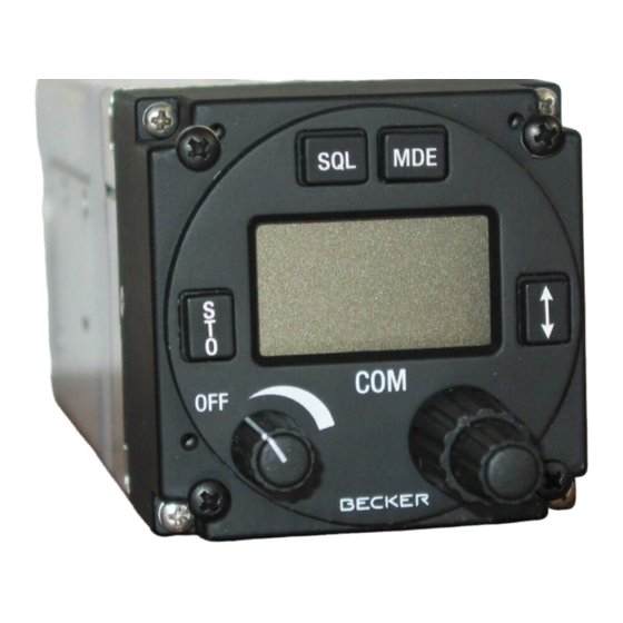
Becker AR4201 Installation Instructions
For standard comm radio harness
Hide thumbs
Also See for AR4201:
- Installation and operation manual (50 pages) ,
- Operating instructions manual (22 pages) ,
- Technical instructions (20 pages)
Advertisement
Quick Links
Installation Instructions for Becker AR4201 STANDARD comm radio harness:
These instructions are for use with a dynamic mic only!
READ ALL THE INSTRUCTIONS BEFORE BEGINNING INSTALLATION.
1) '4201 SPEAK': Solder center conductor to (+) tab on 4 or 8-ohm, 5-watt speaker. Solder the shield wire
to the (-) tab.
2) '4201 AUDIO': Solder the center conductor to the audio hi tab, which is the only contact on the audio
jack. Solder the black shield wire to the ground tab, corresponding to the jack's threaded portion. If
installing this system to two places, these leads may be paralleled to the second place.
3) '4201 PTT = Or, 4201 Mic Hi = Blu, 4201 Mic Lo = Wh': All conductors of this multi-conductor wire go to
the mic jack. Solder the orange striped wire to the push-to-talk tab, which is the 'tallest' contact on the jack.
Solder the blue striped wire to the mic hi tab, which is the 'shorter' contact on the jack. Solder the white
wire to the ground tab corresponding to the jack's threaded portion. If installing this system to two places,
these leads may be paralleled to the second place.
(*) If installing a push-to-talk switch, use the single conductor, shielded wire, marked 'PILOT PTT'. Solder
the center conductor to the same tab as the orange striped wire (PTT = Or) installed in this step. Solder
the black shield wire to the shield wire (Ground = Blk). Route and cut this wire to length and install the
solder sleeve and jumper wire to the shield. Solder the center conductor and shield wire to the tabs of the
customer-provided push-to-talk switch.
4) '4201 AUX IN': Solder the center conductor to the twisted wires on the resistors, already attached to the
small music jack. Solder the shield wire to the short, ground tab on the music jack.
5) '4201 LIGHT': If you wish to activate the backlight on the radio face, solder the 'Light' wire to one tab of
the normally open contacts of a customer-provided switch. Solder a +12 VDC wire to the other contact.
When the contacts close, the backlight in the radio face will be lit. If desired a dimmer pot may be used in
place of the switch. If no lights will be used, cap and stow this wire.
6) '4201 ICS': If you install this unit to two places, grounding this wire will activate the internal intercom
system and allow the two places to communicate with each other. To use the internal intercom, solder this
wire to one tab of a normally open switch and a ground wire to the other tab (both items customer
provided). Close the switch to activate the internal intercom and open it when transmitting on the radio. If
the ICS will not be used, cap and stow this wire.
7) '4201 GROUND': Attach this twisted pair of wires to, either airframe ground or a dedicated avionics
ground. This may be accomplished with solder or by installing a ring terminal and using the appropriate
hardware, as necessary.
8) '4201 POWER': Install an appropriately sized ring terminal and attach it to the 'load' terminal of a 5-amp
circuit breaker.
* ALWAYS check that the power supplied to the radio is correct as per the manufacturer's
requirements. *
9) Connect the 25-socket connector to the back of the radio with the self-contained slide lock.
10) Connect a coax antenna cable from the antenna to the BNC connector at the back of the radio.
Special notes:
These instructions only address the electrical installation of this radio. Follow the manufacturer's
Advertisement

Related Manuals for Becker AR4201


Summary of Contents for Becker AR4201
- Page 1 Installation Instructions for Becker AR4201 STANDARD comm radio harness: These instructions are for use with a dynamic mic only! READ ALL THE INSTRUCTIONS BEFORE BEGINNING INSTALLATION. 1) '4201 SPEAK': Solder center conductor to (+) tab on 4 or 8-ohm, 5-watt speaker. Solder the shield wire to the (-) tab.
- Page 2 instructions for all other aspects of the installation, such as the antenna connections and the mechanical mounting. The speaker or audio (headphones), or both may be used. If the speaker and audio are connected, a switch should be installed on the speaker (+) wire so that the speaker can be switched off if headphones are being used.
Need help?
Do you have a question about the AR4201 and is the answer not in the manual?
Questions and answers