
Related Manuals for NEFF T69S86N0AU


Summary of Contents for NEFF T69S86N0AU
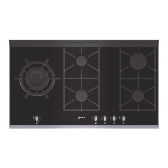
- Page 1 T69S86N0AU This cooktop is for use with Natural Gas and Universal LPG Neff GmbH ß Carl-Wery-Stra e 34 81739 München GMK 10010 Cod. 900 0504214 A AS 4551:2008...
- Page 2 Notes: ..........................................................................................................................................................................................................................................Date installed:....................................Installed by:......................................Compliance Certificate No.:....................................................
-
Page 3: Table Of Contents
Preparing to install ..... . . Clearances ...... - Page 4 - do not pour used oil down the sink. Collect it in a sealed container and take it to an appropriate collection point or, failing that, place it in the rubbish bin (it will end up in a controlled dump;...
-
Page 5: Safety Considerations
Installation and service must be performed by an authorised person. Warnings Do not allow the flame to extend beyond the edge of the cooking utensil. This instruction is based on safety considerations. Do not forget that the unit becomes hot when in use. - Page 6 Important. When using a very large pot, leave a gap of at least 50 mm (2”) to avoid damaging any parts in bench top wood, plastic or other non-heat resistant materials.
- Page 7 Important: Do not cover up the slots at the rear of the cooktop and observe the minimum insertion gap. DANGER, COMBUSTION MAY BE AFFECTED. This appliance is not intended for use by persons (including children) with reduced physical, sensory or...
-
Page 8: Installation
Ø Preparing to install Refer to AS/NZS 5601.1 for piping size details. These built-in hobs are intended to be inserted in a benchtop cutout. Do not stick the hob onto the worktop with silicone. Only an officially authorised technician should connect the appliance. -
Page 9: Clearances
Observe any special conditions imposed by local suppliers (utilities). The specifications of this cooktop are stated on the data label located on the bottom of the cooktop base. A duplicate data label is supplied for adhesion to an... -
Page 10: Installation Of Cooktop Into Kitchen Bench
If an oven is positioned below the cooktop the barrier does not need to be fitted, but a space of 35 mm must be maintained between the underside of the cooktop and the top of the oven. Installation of cooktop... -
Page 11: Gas
Remove plastic cap from gas supply line prior to installation. Fit regulator (N.G.) or a test point (Propane gas) directly to the R 1/2’’ connection as per Fig. 5. and Fig. 6. Direction of gas flow is indicated on the rear of the regulator. -
Page 12: Conversion From Nat. Gas To Propane Gas
Before Leaving- Check all connections for gas leaks with soap and water. DO NOT use a naked flame for detecting leaks. Ignite all burners both individually and concurrently to ensure correct operation of gas valves, burners and ignition. -
Page 13: Changing The Nozzles Of The Large, Medium
Fig. 7 Fig. 8 Changing double- The glass panel and frame are fixed to the rest of the cooktop using a clip mounting system. The following flame burner tips steps must be taken to remove the glass panel and frame: - Remove all the burner covers and pan supports. -
Page 14: Changing The Outer Flame Nozzle
Never use the lever on glass edges which have no trim or frame! - To release the rear clips, carefully raise the entire glass panel and frame, as in Fig.10a. Fig. 10a Changing the outer flame - Loosen the clamp screw to release the bushing by moving it backwards to access the main nozzle easily. -
Page 15: Changing The Inner Flame Nozzle
Changing the inner flame - Unscrew the part M3 from the threaded part M2; to do this, hold the threaded part in the opposite direction. nozzle (fig. 12) - Remove the pipe from the part M2. Fig. b2. - Disassemble the assembly of parts M2 and M4 from part M1. - Page 16 To adjust the minimum flame for N.G. replace the control knob onto the spindle, light the gas and turn the control knob to the small flame position. Screw the adjustment screw anti-clockwise to estabilish a minimum stable flame position.
-
Page 17: Operating Instructions
The gas burners There are indications to show which burner each control knob operates. Fig. 15. Operation It is essential to ensure that all the burner parts and pan supports are correctly installed for the appliance to work correctly. Fig.16-17-18-19. Fig. 17 Fig. -
Page 18: Switching On Automatically
2. Turn the control knob to the required setting. If it does not come on, turn the control knob to the off setting and repeat the steps above. This time, press and hold the control knob for longer (up to 10 seconds). -
Page 19: Warnings
It is normal to hear a slight whistling noise while the burner is operating. When it is first used, it is normal for the burner to give off odours; this does not pose any risk and does not indicate a malfunction; they will disappear in time. -
Page 20: Suitable Pans
“Economy flame” to maintain the required pan temperature. Important: The use of a cooktop leads to the production of heat and moisture in the kitchen. For this reason make sure that the room is properly ventilated.Keep natural ventilation openings, such as windows, open or provide a mechanical ventilation device(e.g. -
Page 21: Cooking Recommendation
Do not place anything, eg. flame tamer, asbestos mat, between pan and pan support as serious damage to the appliance may result. Do not remove the pan support and enclose the burner with a wok stand as this will concentrate and deflect heat onto the hotplate. -
Page 22: Precautions For Use
Pans may tip over. Only use pans with a thick, flat base. Do not cook without using a lid and make sure the lid is properly fitted to avoid wasting energy. Always place the pan right over the burner, not to one side. -
Page 23: Cleaning And Maintenance
Maintenance Always clean off any liquid as soon as it is spilt: you will save yourself any unnecessary effort. Grains of sand that may come from cleaning fruits and vegetables will scratch the glass surface. -
Page 24: Service
Yellow tipping of the hob burner flame. Sooting up of cooking utensils. Burners not lighting properly. Gas valves, which are difficult to turn in case the appliance fails to operate correctly, contact the authorised service provider in your area. -
Page 25: Wiring Diagram
Wiring diagram A. Switch B. Blue wire C. Brown wire D. Terminal E. Ignition module N eff Gmb H T69S86N0AU marks 65/215 47/115 1 30 54,60 In compliance with AS/NZ 3100 and AS 4551 Made in Spain GMK10010... - Page 26 Notes: ........................................................................................................................................................................................................................................................................................................................
Need help?
Do you have a question about the T69S86N0AU and is the answer not in the manual?
Questions and answers