Table of Contents
Advertisement
Quick Links
PH5G-B
13.4 SEER2 Single-Packaged Heat Pump System
with R-454B Refrigerant
Single Phase 2-5 Nominal Tons (Sizes 24-60)
Three Phase 3-5 Nominal Tons (Sizes 36-60)
IMPORTANT: Effective January 1, 2023, all split system and packaged
air conditioners must be installed pursuant to applicable regional
efficiency standards issued by the Department of Energy.
NOTE: Read the entire instruction manual before starting the
installation.
NOTE: Installer: Make sure the Owner's Manual and Service
Instructions are left with the unit after installation.
Table of Contents
Safety Considerations . . . . . . . . . . . . . . . . . . . . . . . . . . . . . . . . . . . . . 1
Introduction. . . . . . . . . . . . . . . . . . . . . . . . . . . . . . . . . . . . . . . . . . . . . 2
Receiving and Installation . . . . . . . . . . . . . . . . . . . . . . . . . . . . . . . . . 2
Transport and Storage Considerations . . . . . . . . . . . . . . . . . . . . . . 2
Leak Dissipation System . . . . . . . . . . . . . . . . . . . . . . . . . . . . . . . 10
Pre-Start-Up . . . . . . . . . . . . . . . . . . . . . . . . . . . . . . . . . . . . . . . . . . . 20
Start-Up. . . . . . . . . . . . . . . . . . . . . . . . . . . . . . . . . . . . . . . . . . . . . . . 20
Maintenance . . . . . . . . . . . . . . . . . . . . . . . . . . . . . . . . . . . . . . . . . . . 27
Troubleshooting . . . . . . . . . . . . . . . . . . . . . . . . . . . . . . . . . . . . . . . . 32
Sequence of Events - Dissipation Mode . . . . . . . . . . . . . . . . . . . 32
Start-Up Checklist. . . . . . . . . . . . . . . . . . . . . . . . . . . . . . . . . . . . . . . 32
Decommissioning. . . . . . . . . . . . . . . . . . . . . . . . . . . . . . . . . . . . . 36
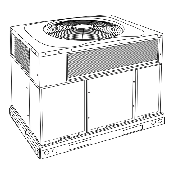
Fig. 1 - Unit PH5G
Safety Considerations
This unit is equipped with electrically powered safety measures. For the
safety measures to be effective, the unit must be electrically powered at
all times after installation, other than when servicing.
WARNING
!
PERSONAL INJURY AND PROPERTY DAMAGE
HAZARD
Continuous fan mode required for proper functioning. Installation must
meet the Required Minimum Dissipation Airflow as outlined in the
Leak Dissipation System section. Follow instructions in the Continuous
Fan Speed Set-Up section to change speeds.
Installation Instruction
A09183
Installation and servicing of this equipment can be hazardous due to
mechanical and electrical components. Only trained and qualified
personnel should install, repair, or service this equipment.
Untrained personnel can perform basic maintenance functions such as
cleaning and replacing air filters. All other operations must be performed
by trained service personnel. When working on this equipment, observe
precautions in the literature, on tags, and on labels attached to or shipped
with the unit and other safety precautions that may apply.
WARNING
!
PERSONAL INJURY AND PROPERTY DAMAGE
HAZARD
For continued performance, reliability, and safety, the only approved
accessories and replacement parts are those specified by the equipment
manufacturer. The use of non-manufacturer approved parts and
accessories could invalidate the equipment limited warranty and result
in fire risk, equipment malfunction, and failure. Please review
manufacturer's instructions and replacement part catalogs available
from your equipment supplier.
Auxiliary devices which may be a POTENTIAL IGNITION SOURCE
shall not be installed in the duct work. Examples of such POTENTIAL
IGNITION SOURCES are hot surfaces with a temperature exceeding
1292°F (700°C) and electric switching devices.
Electrostatic air purifiers installed in the ductwork are permitted, if the
purifier has an airflow sensor.
False ceilings or drop ceilings must not be used as a return air
duct/plenum.
This self-contained unit is already charged with refrigerant for optimum
performance, and shouldn't require any adjustments. Should any
installation/service work on the A2L refrigerant system be needed,
non-sparking tools are required. If the refrigerant system is opened, a
refrigerant detector should be used to check for leaks. Open flames or
other ignition sources should not be present, except during brazing.
Brazing should only take place on refrigerant tubes that are open to the
atmosphere or have been properly evacuated.
Follow all safety codes. Wear safety glasses, protective clothing, and
work gloves. Use quenching cloth for brazing operations. Have a fire
extinguisher available. Read these instructions thoroughly and follow all
warnings or cautions included in literature and attached to the unit.
Consult local building codes, the current editions of the National
Electrical Code (NEC) NFPA 70.
In Canada refer to the current editions of the Canadian Electrical Code
CSA C22.1.
Recognize safety information. This is the safety-alert symbol
you see this symbol on the unit and in instructions or manuals, be alert to
the potential for personal injury. Understand these signal words:
DANGER, WARNING, and CAUTION. These words are used with the
safety-alert symbol. DANGER identifies the most serious hazards which
will result in severe personal injury or death. WARNING signifies
. When
Advertisement
Table of Contents

Related Manuals for Carrier PH5G-B


Summary of Contents for Carrier PH5G-B
-
Page 1: Table Of Contents
PH5G-B 13.4 SEER2 Single-Packaged Heat Pump System with R-454B Refrigerant Single Phase 2-5 Nominal Tons (Sizes 24-60) Three Phase 3-5 Nominal Tons (Sizes 36-60) Installation Instruction IMPORTANT: Effective January 1, 2023, all split system and packaged Installation and servicing of this equipment can be hazardous due to air conditioners must be installed pursuant to applicable regional mechanical and electrical components. -
Page 2: Introduction
Step 1 – Check Equipment hazards which could result in personal injury or death. CAUTION is used to identify unsafe practices which may result in minor personal Identify Unit injury or product and property damage. NOTE is used to highlight The unit model number and serial number are stamped on the unit suggestions which will result in enhanced installation, reliability, or identification plate. - Page 3 PH5G-B: Installation Instruction coil. Do not locate the unit in either a corner or under an overhead obstruction. The minimum clearance under a partial overhang (such as a normal house overhang) is 48 in. (1219 mm) above the unit top. The maximum horizontal extension of a partial overhang must not exceed 48 in.
- Page 4 PH5G-B: Installation Instruction A240010 Fig. 2 – 24-30 Unit Dimensions Manufacturer reserves the right to change, at any time, specifications and designs without notice and without obligations.
- Page 5 PH5G-B: Installation Instruction A240011 Fig. 3 – 36-60 Unit Dimensions Manufacturer reserves the right to change, at any time, specifications and designs without notice and without obligations.
- Page 6 PH5G-B: Installation Instruction A180216 Fig. 4 – Roof Curb Dimensions B (small/common UNIT CATALOG B (large base) base) SIZE NUMBER IN. (mm) IN. (mm) IN. (mm) IN. (mm) IN. (mm) IN. (mm) IN. (mm) IN. (mm) IN. (mm) Small or...
- Page 7 PH5G-B: Installation Instruction A09051 RIGGING WEIGHTS (SMALL CABINET) RIGGING WEIGHTS (LARGE CABINET) Unit Unit Rigging Weight Rigging Weight NOTE: See dimensional drawing for corner weight distribution. Fig. 5 – Rigging Weights Step 4 – Rig and Place Unit Inspection Prior to initial use, and at monthly intervals, all rigging shackles, clevis...
- Page 8 PH5G-B: Installation Instruction Rigging/Lifting of Unit (See Fig. Configuring Units for Downflow (Vertical) Discharge Lifting holes are provided in base rails as shown. WARNING 1. Attach shackles, clevis pins, and straps to the base rails of the unit. Be sure materials are rated to hold the weight of the unit (See ELECTRICAL SHOCK HAZARD Fig.
- Page 9 PH5G-B: Installation Instruction 3. Use flexible transition between rigid ductwork and unit to prevent If the installation requires draining the condensate water away from the transmission of vibration. The transition may be screwed or bolted unit, install a field-supplied 2 -in. (51mm) trap at the condensate to duct flanges.
-
Page 10: Leak Dissipation System
PH5G-B: Installation Instruction High-Voltage Connections Special Procedures for 208-V Operation The unit must have a separate electrical service with a field-supplied, WARNING waterproof disconnect switch mounted at, or within sight from the unit. Refer to the unit rating plate, NEC and local codes for maximum... - Page 11 PH5G-B: Installation Instruction Table 1 – Dissipation Board Test Button Functions Hold Button Time (sec) Function Dissipation Mode for 60 sec 5-29 Display flash code history Flash code 6 3 rapid presses Clear flash code history A test button on the DSB may be used to verify proper dissipation...
- Page 12 PH5G-B: Installation Instruction Transformer Protection e. ELECTRIC HEATING MODE (1.) Thermostat closes circuit R to W/W1, or W2 and R to G. The transformer is of the energy-limiting type. It is set to withstand a There are no on or off delays.
- Page 13 PH5G-B: Installation Instruction Table 4 – Minimum Airflow for Reliable Electric Heater Operation (CFM) SIZE AIRFLOW (CFM) 1025 1250 1400 1710 1800 A09098 Fig. 14 – Typical Installation Manufacturer reserves the right to change, at any time, specifications and designs without notice and without obligations.
- Page 14 PH5G-B: Installation Instruction A240137 Fig. 15 – Connection Wiring Schematics 208/230-1-60 Manufacturer reserves the right to change, at any time, specifications and designs without notice and without obligations.
- Page 15 PH5G-B: Installation Instruction A240138 Fig. 16 – Ladder Wiring Schematics 208/230-1-60 Manufacturer reserves the right to change, at any time, specifications and designs without notice and without obligations.
- Page 16 PH5G-B: Installation Instruction A240139 Fig. 17 – Connection Wiring Schematics - 208/230-3-60 Manufacturer reserves the right to change, at any time, specifications and designs without notice and without obligations.
- Page 17 PH5G-B: Installation Instruction A240140 Fig. 18 – Ladder Wiring Schematics - 208/230-3-60 Manufacturer reserves the right to change, at any time, specifications and designs without notice and without obligations.
- Page 18 PH5G-B: Installation Instruction A240141 Fig. 19 – Connection Wiring Diagram 460-3-60 Manufacturer reserves the right to change, at any time, specifications and designs without notice and without obligations.
- Page 19 PH5G-B: Installation Instruction A240142 Fig. 20 – Ladder Wiring Diagram 460-3-60 Manufacturer reserves the right to change, at any time, specifications and designs without notice and without obligations.
-
Page 20: Pre-Start-Up
PH5G-B: Installation Instruction Pre-Start-Up FAN mode is placed in FAN ON position and shuts down when FAN MODE switch is placed in AUTO position. WARNING (2.) Thermostat: When the room temperature rises to a point that is slightly above the cooling control setting of the thermostat, the... - Page 21 PH5G-B: Installation Instruction 6. Shut off power to unit. WARNING 7. Before beginning recovery of the refrigerant: a. Make sure that handling equipment is available, if needed, to EXPLOSION HAZARD handle the refrigerant recovery cylinders. b. All personal protective equipment is available, and must be used Failure to follow this warning could result in correctly.
- Page 22 PH5G-B: Installation Instruction NOTE: If the problem causing the inaccurate readings is a refrigerant 1. Using Fig. 22, move the two pin DEHUM jumper from the “STD” leak, refer to Check for Refrigerant Leaks section. position to the “DEHUM” position.
- Page 23 PH5G-B: Installation Instruction Continuous Fan Operation WARNING When the DEHUM feature is not used, the continuous fan speed will be the same as cooling fan speed. When the DEHUM feature is used, the PERSONAL INJURY AND PROPERTY DAMAGE continuous fan will operate on IFB “LOW” speed when the DH control HAZARD lead is not energized, or IFB “HIGH”...
- Page 24 PH5G-B: Installation Instruction C03012 Fig. 23 – Typical Heat Pump Operation, Heating Mode Step 3 – Defrost Control Demand Defrost Mode The defrost mode is factory set to an initial 60-minute time interval. It may also be adjusted to an initial interval of 30, 90, or 120 minutes.
- Page 25 PH5G-B: Installation Instruction Table 6 – Dry Coil Air Delivery* - Horizontal and Downflow Discharge Sizes 24-60 ESP (in. W.C.) Unit Size Motor Speed Blue 0.09 0.07 0.06 Pink Med-Low 0.11 0.12 0.12 0.13 0.13 0.14 0.14 0.15 0.15 0.16...
- Page 26 PH5G-B: Installation Instruction Table 7 – Filter Pressure Drop Table (IN. W.C.) Cooling Standard CFM (SCFM) Filter Size in. (mm) Tons 900 1000 1100 1200 1300 1400 1500 1600 1700 1800 1900 2000 2100 2200 600-1400 CFM 2.0, 12x20x1+12x20x1 0.03 0.04 0.05 0.06 0.06 0.07 0.07 0.08 0.08...
-
Page 27: Maintenance
PH5G-B: Installation Instruction Maintenance Indoor Blower and Motor NOTE: All motors are pre-lubricated. Do not attempt to lubricate these To ensure continuing high performance, and to minimize the possibility motors. of premature equipment failure, periodic maintenance must be NOTE: 460 volt units have a stepdown autotransformer that supplies performed on this equipment. - Page 28 PH5G-B: Installation Instruction To properly check or adjust charge, conditions must be favorable for subcooling charging. Favorable conditions exist when the outdoor temperature is between 75_F to 115_F (24_C and 46_C), and the indoor temperature is between 70_F and 80_F (21_C and 27_C). Follow the procedure above.
- Page 29 PH5G-B: Installation Instruction Step 2 – Outdoor Coil, Indoor Coil, and Condensate with the proper electrical instrumentation. Refer to the unit wiring label when making these checkouts. Drain Pan Step 5 – Refrigerant Circuit Inspect the condenser coil, evaporator coil, and condensate drain pan at Inspect all refrigerant tubing connections.
- Page 30 PH5G-B: Installation Instruction WARNING EXPLOSION HAZARD Failure to follow this warning could result in personal injury, death or property damage. Wear safety glasses and gloves when handling refrigerants. Keep torches and other ignition sources away from refrigerant and oils. The scroll compressor pumps refrigerant throughout the system by the interaction of a stationary and an orbiting scroll.
- Page 31 PH5G-B: Installation Instruction FAN GRILLE MOTOR MOTOR SHAFT A08505 MAX DISTANCE BETWEEN TOP OF FAN GRILLE AND BOTTOM OF FAN BLADE “A” Size Fig. 27 – Fan Blade Position Step 12 – Refrigerant System 1. Cover extended roof working area with an impermeable polyethylene (plastic) drip cloth or tarp.
-
Page 32: Troubleshooting
PH5G-B: Installation Instruction Check Defrost Thermostat Flashing 5 The defrost thermostat is usually located on the lowest liquid leaving If the code does not clear after power cycling the system, replace the circuit of the left condenser coil (see Fig. - Page 33 PH5G-B: Installation Instruction Table 11 – Troubleshooting Chart SYMPTOM CAUSE REMEDY Power failure Call power company Fuse blown or circuit breaker tripped Replace fuse or reset circuit breaker Defective contactor, transformer, or high-pressure, Replace component loss-of-charge or low-pressure switch Compressor and condenser fan will not start.
- Page 34 PH5G-B: Installation Instruction Table 12 – Dissipation Board Status Code Descriptions A240111 Manufacturer reserves the right to change, at any time, specifications and designs without notice and without obligations.
- Page 35 PH5G-B: Installation Instruction Start-Up Checklist (Remove and Store in Job Files) I. PRELIMINARY INFORMATION MODEL NO.: ____________________________________________ SERIAL NO.: ____________________________________________ DATE: __________________________________________________ TECHNICIAN: ___________________________________________ II. PRESTART-UP (Insert check mark in box as each item is completed) ( ) VERIFY THAT ALL PACKING MATERIALS HAVE BEEN REMOVED FROM UNIT...
-
Page 36: Decommissioning
Edition Date: 04/24 © 2024 Carrier. All rights reserved. Catalog No: IM-PH5G-02 A Proud Member of the Carrier Family. Replaces: New Manufacturer reserves the right to change, at any time, specifications and designs without notice and without obligations.
Need help?
Do you have a question about the PH5G-B and is the answer not in the manual?
Questions and answers