Table of Contents
Advertisement
Quick Links
INSTALLATION INSTRUCTIONS
14 SEER Single- -Packaged Heat Pump System
Single Phase 2- -5 Nominal Tons (Sizes 24- -60)
Three Phase 3- -5 Nominal Tons (Sizes 36- -60)
IMPORTANT: Effective January 1, 2015, all split system and
packaged air conditioners must be installed pursuant to applicable
regional efficiency standards issued by the Department of Energy.
NOTE:
Read the entire instruction manual before starting the
installation.
NOTE:
Installer: Make sure the Owner's Manual and Service
Instructions are left with the unit after installation.
TABLE OF CONTENTS
. . . . . . . . . . . . . . . . . . . . . . . . . . . . . . . . . . .
. . . . . . . . . . . . . . . . . . . . . . . . . . . . . . . . . .
. . . . . . . . . . . . . . . . . . . . . . . . . . . . . . . . . . . .
. . . . . . . . . . . . . . . . . . . . . . . . . . . . . . . . .
. . . . . . . . . . . . . . . . . . . . . . . . . . . . . . .
. . . . . . . . . . . . . . . . . . . . . . . . . . . . . . . . . . . . . .
. . . . . . . . . . . . . . . . . . . . . . . . . . . . . . . . . . . . .
. . . . . . . . . . . . . . . . . . . . . . . . . . . . . . . . .
. . . . . . . . . . . . . . . . . . . . . . . . . . . . . . . . .
. . . . . . . . . . . . . . . . . . . . . . . . . . . . . . . . . . . . . .
. . . . . . . . . . . . . . . . . . . . . . . . . . . .
. . . . . . . . . . . . . . . . . . . . . . . . . . .
. . . . . . . . . . . . . . . . . . . . . . . . . . . .
. . . . . . . . . . . . . . . . . . . . . . . . . . .
. . . . . . . . . . . . . . . . . . . . . . . . . . .
. . . . . . . . . . . . . . . . . . . . . . . . . . . . . . . . . . .
. . . . . . . . . . . . . . . . . . . . . . . . . . . . . . . . . . . . .
. . . . . . . . . . . . . . . . . . . . . . . . . . . . .
. . . . . . . . . . . . . . . . . . . . . . . . . . . . . . . . . . .
. . . . . . . . . . . . . . . . . . . . . . . . . . . . . . . . . . . . . . .
. . . . . . . . . . . . . . . . . . . . . . . . . . . . . . . .
. . . . . . . . . . . . . . . . . . . . . . . . . . . . . . . . . . . . . . . .
. . . . . . . . . . . . . . . . . . . . . . . . . . .
. . . . . . . . . . . . . . . . . . . . . . . . . . . . . . . . . . . . .
. . . . . . . . . . . . . . . . . . . . . . . . . . . . . . . . .
. . . . . . . . . . . . . . . . . . . . . . . . . . . . . . . . . . .
. . . . . . . . . . . . . . . . . . . . . . . . . . . . . . . . .
. . . . . . . . . . . . . . . . . . . . . . . . . . . . .
with R- -410A Refrigerant
PHD4 Series F and WPH4 Series B
PAGE
. . . . . . . . . . . . . . . . . . . . . . . . .
. . . . . . . . . . . . . . . . .
2- -11
. . . . .
. . . . . . . . . . . . . . . . . . . . .
. . . . . . . . . . . . . . . . . . . . . . . .
. . . . . . . . . . . . . . . . . . . . . . . .
. . . . . . . . . . . . . .
. . . . . . . . . . . . . . . . . . . . . . .
. . . . . . . . . . . . . . .
19- -22
. . . . . . . .
. . . . . . . . . . . . . . . . . . . . . . . . .
. . . . . . . . . . . .
. . . . . . . . . . . . . .
. . . . . . . . . . . . . . . . . . . . . . . .
30- -35
. . . . . .
. . . . . . . . . . . . . . . . . . . . . . .
. . . . . . . . . . . . . . . . . . . .
Specifications are subject to change without notice.
1
2
2
2
2
2
2
2
2
8
8
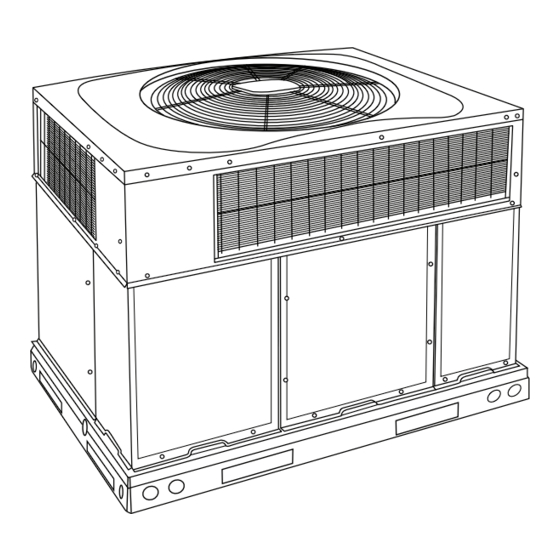
Fig. 1 - - Unit PHD4 and WPH4
8
(Some units may vary in appearance)
9
9
10
10
. . . . . . . . . . . . . . . . . . . . . . . . . . . . . . . . . . . .
10
11
11
11
11
11
11
19
19
SAFETY CONSIDERATIONS
19
20
Installation and servicing of this equipment can be hazardous due
20
to mechanical and electrical components. Only trained and
20
qualified personnel should install, repair, or service this equipment.
21
Untrained personnel can perform basic maintenance functions such
22
as cleaning and replacing air filters. All other operations must be
22
performed by trained service personnel. When working on this
equipment, observe precautions in the literature, on tags, and on
30
labels attached to or shipped with the unit and other safety
30
precautions that may apply.
33
Follow all safety codes. Wear safety glasses, protective clothing,
33
and work gloves. Use quenching cloth for brazing operations.
33
Have a fire extinguisher available. Read these instructions
33
thoroughly and follow all warnings or cautions included in
33
33
33
34
. . . . . . . . . . . . . . . . . . . . . . . . . . . . . .
. . . . . . . . . . . . . . . . . . . . . . . . . . . . . . . .
. . . . . . . . . . . . . . . . . . . . . . . . . . . . . . . . .
. . . . . . . . . . . . . . . . . . . . . . . . . . .
. . . . . . . . . . . . . . . . . . . . . .
. . . . . . . . . . . . . . . . . . . . . . . . . . . . . . . .
. . . . . . . . . . . . . . . . . . . . . . . . . . . .
. . . . . . . . . . . . . . . . . . . . . . . . .
. . . . . . . . . . . . . . . . . . . . . . . . . . . . . .
. . . . . . . . . . . . . . . . . . . . . . . . . . . .
51801200404
05/2018
A09034
34
. . . . . . .
34
34
34
35
. . . .
35
35
35
35
35
35
35
35
Advertisement
Table of Contents

Related Manuals for Carrier PHD4 F Series


Summary of Contents for Carrier PHD4 F Series
-
Page 1: Table Of Contents
INSTALLATION INSTRUCTIONS 14 SEER Single- -Packaged Heat Pump System with R- -410A Refrigerant Single Phase 2- -5 Nominal Tons (Sizes 24- -60) Three Phase 3- -5 Nominal Tons (Sizes 36- -60) PHD4 Series F and WPH4 Series B IMPORTANT: Effective January 1, 2015, all split system and packaged air conditioners must be installed pursuant to applicable regional efficiency standards issued by the Department of Energy. -
Page 2: Introduction
literature and attached to the unit. Consult local building codes, the the downflow panels before rigging and lifting into place. The current editions of the National Electrical Code (NEC) NFPA 70. panel removal process may require the unit to be on the ground. In Canada refer to the current editions of the Canadian Electrical Step 2 —... - Page 3 A150561 Fig. 2 - - PHD4 24- -30 Unit Dimensions 51801200404 Specifications are subject to change without notice.
- Page 4 A150550 Fig. 3 - - WPH4 24- -30 Unit Dimensions 51801200404 Specifications are subject to change without notice.
- Page 5 A150562 Fig. 4 - - PHD4 36- -60 Unit Dimensions 51801200404 Specifications are subject to change without notice.
- Page 6 A150551 Fig. 5 - - WPH4 36- -60 Unit Dimensions 51801200404 Specifications are subject to change without notice.
- Page 7 Dashed lines show cross support location for large basepan units. HVAC unit HVAC unit basepan base rails Sealing Gasket Roofcurb Anchor screw Wood nailer* Flashing field supplied Roofcurb* Insulation (field supplied) Roofing material field supplied Cant strip field supplied SMALL/COMMON CURB A09413 *Provided with roofcurb A09090...
-
Page 8: Rig And Place Unit
CAUTION - NOTICE TO RIGGERS PRUDENCE - AVIS AUX MANIPULATEUR ACCESS PANELS MUST BE IN PLACE WHEN RIGGING. PANNEAUX D'ACCES DOIT ÊTRE EN PLACE POUR MANIPULATION. Use top skid as spreader bar. / Utiliser la palette du haut comme barre de répartition DUCTS MINIMUM HEIGHT: 36"... -
Page 9: Select And Install Ductwork
Step 5 — Select and Install Ductwork CONFIGURING UNITS FOR DOWNFLOW (VERTICAL) DISCHARGE The design and installation of the duct system must be in accordance with the standards of the NFPA for installation of WARNING non- -residence type air conditioning and ventilating systems, NFPA 90A or residence- -type, NFPA 90B and/or local codes and ELECTRICAL SHOCK HAZARD ordinances. -
Page 10: Provide For Condensate Disposal
3. Use flexible transition between rigid ductwork and unit to at outlet end of the 2- -in. (51 mm) trap. (See Fig. 11) Do not prevent transmission of vibration. The transition may be undersize the tube. Pitch the drain tube downward at a slope of at screwed or bolted to duct flanges. -
Page 11: Special Procedures For 208- -V Operation
control voltage wires), use no. 16 AWG color- -coded, insulated (35 C minimum) wires. HIGH VOLTAGE Standard Connections POWER LEADS POWER (SEE UNIT WIRING SUPPLY LABEL) Locate the eight (nine on 3- -phase) low voltage thermostat leads in 3-PHASE SHOWN 24 volt splice box. - Page 12 Table 1 – Physical Data Unit Size Shipping Weight (lb) (kg) Compressor Quantity Type Scroll Refrigerant R-410A Refrigerant Quantity (lb) 11.2 11.9 Quantity (kg) Indoor Ac- curater, Indoor TXV, Out- Refrigerant Metering Device Indoor TXV, Outdoor Dual Accuraters Outdoor door Dual Ac- Dual Ac- curaters curaters...
- Page 13 A150518 Fig. 14 - - Connection Wiring Schematics 208/230- -1- -60 51801200404 Specifications are subject to change without notice.
- Page 14 A150519 Fig. 12 Cont. - - Ladder Wiring Schematics 208/230- -1- -60 51801200404 Specifications are subject to change without notice.
- Page 15 A150520 Fig. 15 - - Connection Wiring Schematics - - 208/230- -3- -60 51801200404 Specifications are subject to change without notice.
- Page 16 A150521 Fig. 13 Cont. - - Ladder Wiring Schematics - - 208/230- -3- -60 51801200404 Specifications are subject to change without notice.
- Page 17 A150522 Fig. 16 - - Connection Wiring Diagram 460- -3- -60 51801200404 Specifications are subject to change without notice.
- Page 18 A150523 Fig. 14 Cont. - - Ladder Wiring Diagram 460- -3- -60 51801200404 Specifications are subject to change without notice.
-
Page 19: Pre- -Start- -Up
PRE- - START- - UP START- - UP Checking Cooling and Heating Control Operation WARNING Start and check the unit for proper control operation as follows: (1.) Place room thermostat SYSTEM switch or MODE FIRE, EXPLOSION, ELECTRICAL SHOCK AND control in OFF position. Observe that blower ENVIRONMENTAL HAZARD motor starts when FAN mode is placed in FAN ON position and shuts down when FAN MODE switch... -
Page 20: Start- -Up Adjustments
Step 2 — Start- -Up Adjustments a. Outdoor ambient- -air temperature (F [C] db). b. Liquid line temperature (F [C]) at TXV. Complete the required procedures given in the Pre- -Start- -Up section before starting the unit. Do not jumper any safety devices c. -
Page 21: Continuous Fan Operation
NOTE: If accessory electric heat is installed, and the electric heat 1. Move the two pin DEHUM jumper located on control board (see Fig. 18) from the “STD” position to the fan speed is chosen to be the same as the normal cooling fan speed, “DEHUM”... -
Page 22: Defrost Control
HIGH R13 C8 AB A15 D5 D3 R3 R5 R6 R W2 Y W3 W3 W2 W2 C SSTZ-8 A09059 Fig. 18 - - Interface Fan Board (IFB) INDOOR COIL OUTDOOR COIL TXV in Bypass Position HP S Metering Position LEGEND HPS –... - Page 23 51801200404 Specifications are subject to change without notice.
- Page 24 51801200404 Specifications are subject to change without notice.
- Page 25 51801200404 Specifications are subject to change without notice.
- Page 26 51801200404 Specifications are subject to change without notice.
- Page 27 51801200404 Specifications are subject to change without notice.
- Page 28 51801200404 Specifications are subject to change without notice.
- Page 29 51801200404 Specifications are subject to change without notice.
-
Page 30: Maintenance
MAINTENANCE Indoor Blower and Motor NOTE: All motors are pre- -lubricated. Do not attempt to lubricate To ensure continuing high performance, and to minimize the these motors. possibility of premature equipment failure, periodic maintenance must be performed on this equipment. This heat pump unit should NOTE: 460 volt units have a stepdown autotransformer that be inspected at least once each year by a qualified service person. - Page 31 Superheat charging table is derived from optimum performance point. (95_F [35_C] outdoor ambient and (80_F [27_C] dry bulb; 67_F [19_C] wet bulb indoor condition.) Where a dash( --- ---) appears do not attempt to check charge or charge unit under these conditions using the superheat method. (Weigh in method should be used.) A150625 To properly check or adjust charge, conditions must be favorable for subcooling charging.
- Page 32 OUTDOOR FAN RELAY DEFROST THERMOSTAT MUST BE CLOSED BEFORE DEFROST TIMER BEGINS T1 - ENABLES DEFROST Y OUTPUT TO PRESSURE SWITCHES AND CONTACTOR TIMER.MUST BE ENERGIZED FOR DEFROST TIMER TO START C - COMMON O - REVERSING VALVE SPEEDUP THERMOSTAT INPUTS A150622 Fig.
-
Page 33: Outdoor Coil, Indoor Coil, & Condensate Drain Pan
Step 2 — Outdoor Coil, Indoor Coil, and Step 6 — Indoor Airflow Condensate Drain Pan The heating and/or cooling airflow does not require checking unless improper performance is suspected. If a problem exists, be Inspect the condenser coil, evaporator coil, and condensate drain sure that all supply- -air and return- -air grilles are open and free pan at least once each year. -
Page 34: Loss Of Charge Switch
FAN GRILLE MOTOR MOTOR SHAFT A08505 MAX DISTANCE BETWEEN TOP OF FAN GRILLE AND BOTTOM OF FAN BLADE “A” SIZE Fig. 24 - - Fan Blade Position Step 9 — Loss of Charge Switch WARNING This switch is located on the liquid line and protects against low suction pressures caused by such events as loss of charge, low EXPLOSION HAZARD airflow across indoor coil, dirty filters, etc. -
Page 35: Compressor Oil
Check Defrost Thermostat This system uses R- -410A refrigerant which has higher operating pressures than R- -22 and other refrigerants. No other refrigerant The defrost thermostat is usually located on the lowest liquid may be used in this system. Gage set, hoses, and recovery system leaving circuit of the left condenser coil (see Fig. - Page 36 R- -410A QUICK REFERENCE GUIDE R- -410A refrigerant operates at 50- -70 percent higher pressures than R- -22. Be sure that servicing equipment and replacement components are designed to operate with R- -410A R- -410A refrigerant cylinders are rose colored. Recovery cylinder service pressure rating must be 400 psig, DOT 4BA400 or DOT BW400.
- Page 37 Table 11 – Troubleshooting Chart SYMPTOM CAUSE REMEDY Power failure Call power company Fuse blown or circuit breaker tripped Replace fuse or reset circuit breaker Defective contactor, transformer, or high--pressure, Replace component loss--of--charge or low--pressure switch Compressor and condenser fan will not start. Insufficient line voltage Determine cause and correct Incorrect or faulty wiring...
- Page 38 START- -UP CHECKLIST (Remove and Store in Job Files) I. PRELIMINARY INFORMATION MODEL NO.: SERIAL NO.: DATE: TECHNICIAN: II. PRESTART- -UP (Insert check mark in box as each item is completed) ( ) VERIFY THAT ALL PACKING MATERIALS HAVE BEEN REMOVED FROM UNIT ( ) REMOVE ALL SHIPPING HOLD DOWN BOLTS AND BRACKETS PER INSTALLATION INSTRUCTIONS ( ) CHECK ALL ELECTRICAL CONNECTIONS AND TERMINALS FOR TIGHTNESS ( ) CHECK THAT INDOOR (EVAPORATOR) AIR FILTER IS CLEAN AND IN PLACE...
Need help?
Do you have a question about the PHD4 F Series and is the answer not in the manual?
Questions and answers