
Subscribe to Our Youtube Channel
Related Manuals for Mankenberg UV 7.5


Summary of Contents for Mankenberg UV 7.5
- Page 1 Original operating manual Back pressure regulators Originalbetriebsanleitung Überströmventil UV 7.5 UV 7.5-4.X.241 Issue 22.05.2024 Made in Germany...
-
Page 2: Table Of Contents
10.2.2 Starting point / preparatory activities..................18 10.2.3 Removing the spring cap ......................19 10.2.4 Removing the device ........................ 19 10.2.5 Maintaining the device ......................20 10.2.6 Final activities ........................... 23 10.3 Torques ..............................24 UV 7.5-4.X.241 Issue 22.05.2024 Made in Germany... - Page 3 14.1.3 Check for damage and deformation..................29 14.1.4 Check for leakage ........................29 15 Information on REACH and RoHS ......................30 15.1 Declaration on the REACH Regulation 1907/2006 ................30 15.2 Declaration on the RoHS Directive 2011/65/EU .................. 30 UV 7.5-4.X.241 Issue 22.05.2024 Made in Germany...
- Page 4 10.2.1 Benötigtes Werkzeug / Material ....................44 10.2.2 Ausgangslage / vorbereitende Tätigkeiten................44 10.2.3 Demontage der Federhaube..................... 45 10.2.4 Demontage des Gerätes......................46 10.2.5 Warten des Gerätes........................47 10.2.6 Abschließende Tätigkeit......................49 10.3 Drehmomente ............................50 UV 7.5-4.X.241 Issue 22.05.2024 Made in Germany...
- Page 5 14.1.2 Korrosion prüfen ........................55 14.1.3 Beschädigung und Verformungen überprüfen ................55 14.1.4 Auf Leckage prüfen........................55 15 REACH- und RoHS-Auskunft ........................56 15.1 Erklärung zur REACH-Verordnung 1907/2006 ..................56 15.2 Erklärung zur RoHS-Richtlinie 2011/65/EU ..................56 UV 7.5-4.X.241 Issue 22.05.2024 Made in Germany...
-
Page 6: Intended Use
The valve is designed and constructed for the conditions specified when the order is placed. The specified design criteria on the nameplate must correspond to the actual operating conditions. If the operating conditions or the application change, Mankenberg must be consulted without fail! Use exclusively maintenance kits and spare parts from Mankenberg. -
Page 7: Safety
Original operating manual Back pressure regulators UV 7.5 2 Safety 2.1 Explanation of the warning notices Safety and warning notices denote safety-related information. The operating manual differentiates between the following hazard levels. DANGER Fatal injuries Denotes a hazardous situation. Failure to observe these warnings may result in serious injuries or death. -
Page 8: Personnel Qualification
Original operating manual Back pressure regulators UV 7.5 2.3 Personnel qualification Only trained and instructed specialist personnel may work with the valve. These personnel must: » be familiar with the valid accident prevention regulations, » have read and understood the operating manual, »... -
Page 9: General Notes
Original operating manual Back pressure regulators UV 7.5 3 General notes This operating manual is intended as instructions for using the valve safely. It is binding for transport, storage, installation, commissioning, operation, maintenance and repair. Only work described in this operating manual may be carried out. -
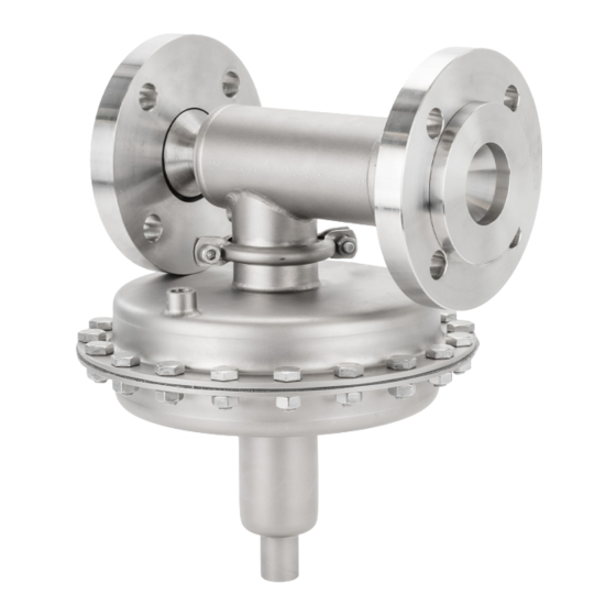
Page 10: General View
Original operating manual Back pressure regulators UV 7.5 5 General view Outlet Bonnet Inlet Adjusting screw Body Sense line connection 6 Nameplate Year of manufacture Order number Type designation Item number Adjustment range Serial number Min / max temperature Nominal diameter DN / max. permissible... -
Page 11: Transport, Handling And Storage
Original operating manual Back pressure regulators UV 7.5 7 Transport, handling and storage » The valve is usually not stable. Handle the valve carefully so that it does not tip over during transport or storage. » During transport and storage, protect the valve against external influences such as impacts, moisture and dirt. -
Page 12: Storage Period
Original operating manual Back pressure regulators UV 7.5 Storage period All parts have a shelf life of 10 years, with the exception of elastomers. The following criteria have an effect on the storage period: » Storage conditions temperature and humidity, »... -
Page 13: Nozzle Loads
Original operating manual Back pressure regulators UV 7.5 Safety valve The control side needs to have a safety valve installed that is measured and adjusted so that the smaller of the two following pressures is used as the set pressure: »... -
Page 14: Installation
Original operating manual Back pressure regulators UV 7.5 There are a maximum of six components of additional external loads: FX, FY, FZ, MX, MY, MZ. Torsion is only significant for very large nozzle diameters and very small cylinder wall thickness. Lateral forces are of secondary importance. -
Page 15: Procedure
Original operating manual Back pressure regulators UV 7.5 » The valve is clean and free of damage. If needed, blow out connecting pieces with clean compressed air. » CAUTION! Do not install damaged valves! Contact the manufacturer, see section Contact [Page 24]. -
Page 16: Operation
Original operating manual Back pressure regulators UV 7.5 Strainer Pressure gage Shut-off valve Sense line Back pressure regulator Leakage line (optional) Safety valve DANGER! During the work, no persons other than the person carrying out the work may be in the danger zone. -
Page 17: Maintenance
Original operating manual Back pressure regulators UV 7.5 NOTICE Risk of material damage caused by frost Frozen liquids can cause unreliable control behavior, failure or damage to the valve. If the valve is installed in rooms that are not frost-free, suitable measures must be taken during plant shutdowns. -
Page 18: Replace Of The Maintenance Kit
Original operating manual Back pressure regulators UV 7.5 The maintenance plan is a recommendation, which is to be supplemented based on how effective the user has found (and continues to find) it to be under the operating conditions. Type of maintenance... -
Page 19: Removing The Spring Cap
Original operating manual Back pressure regulators UV 7.5 Removing the spring cap 1. Release the spring. To do so, loosen the adjusting screw (30.10) (by turning it counterclockwise). The adjusting screw is loosened until any resistance can no longer be felt. -
Page 20: Maintaining The Device
Original operating manual Back pressure regulators UV 7.5 1. Clamp the device in the vise such that the valve 30.1 stem is accessible. 30.6 2. Unscrew and store the nuts (30.1) of the diaphragm disc (2 nuts). 3. Lift the diaphragm disc (30.6) off the stem (5). - Page 21 Original operating manual Back pressure regulators UV 7.5 Removing the internal parts 1. Open the split pin (17) of the lever pin (8). Remove the lever pin (8) from the drilled hole in the valve frame (2). 2. Remove the valve frame (2) from the valve cone (3).
- Page 22 Original operating manual Back pressure regulators UV 7.5 Check the ease of movement of the valve mechanism. The ease of movement of the lever mechanism and valve stem must be checked. The lever mechanism must move easily across the entire stroke path.
-
Page 23: Final Activities
Original operating manual Back pressure regulators UV 7.5 5. Place on the stem (5) such that there is no 30.7 tension. Diaphragm disc (30.9) 30.1 Diaphragm (30.8) Diaphragm disc (30.7) 30.6 Diaphragm disc (30.6) Ensure that the mechanism moves easily. -
Page 24: Torques
For orders and questions, Mankenberg Service will be glad to assist you, see Section Contact [Page 24]. Contact In the event of malfunctions that cannot be eliminated on site, Mankenberg’s After Sales Service is happy to provide further assistance: Mankenberg GmbH Spenglerstraße 99 D-23556 Lübeck | Germany... -
Page 25: Troubleshooting, Trouble Shooting And Repairing
Original operating manual Back pressure regulators UV 7.5 11 Troubleshooting, trouble shooting and repairing Help in case of faults If the faults cannot be eliminated on site, get in touch with the manufacturer (Mankenberg). Malfunctions Cause Remedy Leakage at the profile clamp /... -
Page 26: Procedure
Original operating manual Back pressure regulators UV 7.5 » Allow valve to cool down. » Decontaminate the valve. Procedure 1. Loosen connections. 2. Remove the valve from the pipe. 12.2 Decommissioning DANGER Bursting hazard and risk of material damage When the operating medium is enclosed in the piping and valve and simultaneous heating takes place, unexpected pressure rise beyond acceptable levels may result. -
Page 27: Disposal
Original operating manual Back pressure regulators UV 7.5 12.3 Disposal » Grease and oils are substances that are hazardous to water and must not be released into the environment. They must be disposed of properly. » Dismantle the valve and dispose of it properly or recycle it separately. -
Page 28: Check Set Inlet Pressure
Original operating manual Back pressure regulators UV 7.5 Tests while operation is ongoing: Measure/type of Work to be done Monthly Yearly maintenance Functional control Check set inlet pressure Visual inspection Check for corrosion Visual inspection Check for leaks Visual inspection... -
Page 29: Check For Damage And Deformation
Original operating manual Back pressure regulators UV 7.5 » If corrosion is found, consult with the manufacturer and implement measures. » If no corrosion is found, reinstall the valve and put it into operation. Check for damage and deformation 1_Preparation / starting point »... -
Page 30: Information On Reach And Rohs
0.1% (w/w) in accordance with the Candidate List (REACH Regulation, Article 33); as per January 2021. 15.2 Declaration on the RoHS Directive 2011/65/EU Mankenberg products are not electrical or electronic equipment and therefore do not fall within the scope of RoHS Directive 2011/65/EU (RoHS, Article 2, paragraph 1 or Annex I). -
Page 31: Bestimmungsgemäße Verwendung
Die Armatur ist für die bei der Bestellung angegebenen Bedingungen ausgelegt und konstruiert. Die angegebenen Auslegungskriterien auf dem Typenschild müssen den realen Einsatzbedingungen entsprechen. Ändern sich Einsatzbedingungen oder Anwendung, ist Rücksprache mit dem Hersteller Mankenberg zu halten. Verwenden Sie ausschließlich Wartungssätze und Ersatzteile der Firma Mankenberg! 1.1 Einsatzbereich... -
Page 32: Sicherheit
Verbrennungsgefahr beim Berühren heißer oder kalter Oberflächen oder durch austretendes Medium aus der Armatur. Durch heißes oder kaltes Medium kann die Oberfläche der Armatur heiß oder kalt sein! Persönliche Schutzausrüstung tragen, je nach Medium: Haut- oder Augenschutz. Sicherheitsmaßnahmen des Betreibers beachten. UV 7.5-4.X.241 Stand 22.05.2024 Made in Germany... -
Page 33: Personalqualifikation
ätzenden Medien. 2.5 Bauliche Veränderung Bauliche Veränderungen am gesamten Lieferumfang können die Sicherheit des Produktes beeinträchtigen. Deshalb sind bauliche Veränderungen unzulässig und dürfen keinesfalls ohne Rücksprache mit dem Hersteller vorgenommen werden. UV 7.5-4.X.241 Stand 22.05.2024 Made in Germany... -
Page 34: Allgemein
» ein sicherer Umgang mit dem Betriebsmedium gewährleistet ist (z.B. Gefahren durch Druck, Kontamination, Feuchtigkeit). 4 Angewandte Normen und Richtlinien Die Konstruktion des vorliegenden Produktes erfolgt nach Regelwerk AD 2000 ohne Merkblatt S1 und S2. UV 7.5-4.X.241 Stand 22.05.2024 Made in Germany... -
Page 35: Übersicht
Überströmventil UV 7.5 5 Übersicht Ausgang Federhaube Eingang Stellschraube Gehäuse Steuerleitungsanschluss 6 Typenschild Herstellungsjahr Auftragsnummer Typenbezeichnung Artikelnummer Einstellbereich Seriennummer Temperatur min / max Nennweite DN / max. zulässiger Druck PS Herstellungsort -Wert Durchflussrichtung Gehäusewerkstoff UV 7.5-4.X.241 Stand 22.05.2024 Made in Germany... -
Page 36: Transport, Handhabung Und Lagerung
» Vor Regen, Nässe, Sonnenlicht und aggressiven Medien schützen. » Nach längerem Einlagern der Armatur den kompletten Wartungssatz wechseln! Lagerungsbedingungen Lagerungstemperatur 15 bis 25 °C. Luftfeuchtigkeit (normal bis trocken) 40 bis 60 %. UV 7.5-4.X.241 Stand 22.05.2024 Made in Germany... -
Page 37: Lagerungsdauer
Für Montage, Wartung sowie dichten Systemabschluss sind vor und hinter dem Überströmventil Absperrorgane vorzusehen. Überströmventil Das Überströmventil regeln den eingestellten, konstanten Druck vor dem Ventil. Eine Druckfeder hält das Ventil geschlossen, es öffnet bei steigendem Vordruck. UV 7.5-4.X.241 Stand 22.05.2024 Made in Germany... -
Page 38: Stutzenlasten
Gefahr von Sachschäden durch erhöhte Stutzenlasten Nicht eingehaltene Stutzenlasten führen zur Beschädigung der Armatur. Beschädigte Armaturen können im Betrieb in Ihrer Funktion eingeschränkt sein oder zu Undichtigkeiten führen. Die angegebenen Stutzenlasten dürfen nicht überschritten werden. UV 7.5-4.X.241 Stand 22.05.2024 Made in Germany... - Page 39 Es gibt maximal sechs Komponenten zusätzlicher äußerer Lasten: FX, FY, FZ, MX, MY, MZ. Torsion ist nur bei sehr großen Stutzendurchmessern und sehr kleiner Zylinderwanddicke von Bedeutung. Querkräfte sind von untergeordneter Bedeutung. Tabelle Stutzenlasten Stutzenlasten bei TS +180 °C My [Nm] Mz [Nm] Fx [N] UV 7.5-4.X.241 Stand 22.05.2024 Made in Germany...
-
Page 40: Einbau
» Die Armatur ist sauber und unbeschädigt, ggf Anschlussstutzen mit sauberer Druckluft ausblasen. » VORSICHT! Beschädigte Armaturen nicht einbauen! Kontaktieren Sie den Hersteller, siehe Kapitel Kontakt [Seite 50]. » Innenteile der Armatur sind frei von Flüssigkeit (z.B. Kondenswasser). UV 7.5-4.X.241 Stand 22.05.2024 Made in Germany... -
Page 41: Vorgehensweise
» Das Sicherheitsventil ist in Betrieb und sichert den vordruckseitigen Anlagenbereich. » Die Absperrorgane vordruckseitig und hinterdruckseitig sind geschlossen. Vorgehensweise Schmutzfänger Manometer Absperrventil Steuerleitung Überströmventil Leckleitung (optional) Sicherheitsventil GEFAHR! Während der Arbeiten dürfen sich außer der durchführenden Person, keine weiteren Personen im Gefahrenbereich aufhalten. UV 7.5-4.X.241 Stand 22.05.2024 Made in Germany... -
Page 42: Betrieb
Hinterdruck (MAWP outlet) darf beliebig oft im Druck schwanken. HINWEIS Gefahr von Sachschäden durch erhöhten Verschleiß Flashing und Kavitation sind unzulässig. Bei Geräuschzunahme oder Volumenstromabnahme ist der Hersteller Mankenberg zu kontaktieren. HINWEIS Gefahr von Sachschäden verursacht durch Frost Gefrorene Flüssigkeiten können zu unzuverlässigem Regelverhalten, Ausfall oder Beschädigung der Armatur führen. -
Page 43: Wartung
Die selbsttätige Funktion der Armatur benötigt Wartung für die einwandfreie Funktion. Wichtig ist, dass Wartungsarbeiten geplant werden und in periodischen Abständen erfolgen. Abhängig von den Eigenschaften des Mediums und den Betriebsumständen in der Anlage ist eine Wartung jährlich oder auch in kürzeren Abständen durchzuführen. UV 7.5-4.X.241 Stand 22.05.2024 Made in Germany... -
Page 44: Austausch Des Wartungssatzes
Benötigtes Werkzeug / Material » Verstellschlüssel » Innensechskantschlüssel » Maulschlüssel » Schraubstock Ausgangslage / vorbereitende Tätigkeiten » Die Armatur ist aus der Anlage ausgebaut, siehe Kapitel Ausbau. » Immer den kompletten Wartungssatz austauschen! UV 7.5-4.X.241 Stand 22.05.2024 Made in Germany... -
Page 45: Demontage Der Federhaube
30.3 (30.3) der Federhaube lösen. Die Schrauben und Muttern aufbewahren. 30.10 3. Federhaube (30) abheben. In der Federhaube befindet sich das Federmodul mit der Stellschraube, diese mit abheben und aufbewahren. 30.1 30.6 30.8 UV 7.5-4.X.241 Stand 22.05.2024 Made in Germany... -
Page 46: Demontage Des Gerätes
8. Einschraubsitz (6) mit Innensechskantschlüssel (SW17) lösen und entnehmen. 9. Nach dem Lösen des Einschraubsitzes (6) sind die Innenteile des Ventils (2) (3) (4) (5) frei und können aus dem Gehäuse (1) entnommen werden. UV 7.5-4.X.241 Stand 22.05.2024 Made in Germany... -
Page 47: Warten Des Gerätes
Gehäuseeingangs einsetzen. Durch Drehen im Uhrzeigersinn mit leichtem Druck in die Bohrung einführen. Dabei beachten, dass der Einschraubsitz (6) die Ausrichtung der Innenteile nicht verändert. 6. Einschraubsitz bis zum Anschlag einschrauben und handfest anziehen. UV 7.5-4.X.241 Stand 22.05.2024 Made in Germany... - Page 48 Einschraubsitz lösen und die Ausrichtung der Hebelmechanik korrigieren. Danach Einschraubsitz wieder anziehen. 3. Membrangehäuse 30.5) aufsetzen und ausrichten. Dabei auf die korrekte Position des Steueranschlusses achten, dieser sollte an derselben Position sein wie vorher. 4. Profilschelle (15) montieren. UV 7.5-4.X.241 Stand 22.05.2024 Made in Germany...
-
Page 49: Abschließende Tätigkeit
» Die Stellschraube bewegt sich sichtbar in Richtung der Schwerkraft. 10. Stellschraube (30.10) im Uhrzeigersinn drehen bis ein Widerstand zu spüren ist. Abschließende Tätigkeit » Armatur einbauen » Betriebspunkt einstellen, siehe Kapitel Inbetriebnahme und Betriebspunkt einstellen [Seite 41] UV 7.5-4.X.241 Stand 22.05.2024 Made in Germany... -
Page 50: Drehmomente
Schrauben an der Federhaube (Pos. 30.2) maximal 25 Nm 10.4 Ersatz- und Verschleißteile In jedem Fall sind Wartungssätze und Ersatzteile von Mankenberg zu verwenden. Bei Bestellungen und Fragen hilft der Mankenberg Service gerne weiter, siehe Kapitel Kontakt [Seite 50]. Kontakt Bei Störungen, die vor Ort nicht behoben werden können, hilft Ihnen der After Sales Service gerne weiter: Mankenberg GmbH Spenglerstraße 99... -
Page 51: Fehlersuche, Störungsbeseitigung Und Reparatur
Originalbetriebsanleitung Überströmventil UV 7.5 11 Fehlersuche, Störungsbeseitigung und Reparatur Hilfe bei Störungen Sollten die Störungen vor Ort nicht behoben werden können, kontaktieren Sie den Hersteller Mankenberg. Störungen Ursache Abhilfe Leckage an der Profilschelle / Lose Schraubverbindungen, Schraubverbindungen defekte Dichtung / Membrane. -
Page 52: Vorbereitung
3. Überströmventil drucklos machen. 4. Druck im Vordruckbereich und im Hinterdruckbereich über sichere Öffnungseinrichtungen entlasten. 5. Sinkende Drücke über die bauseitigen Druckanzeigegeräte prüfen. 6. Medium im Vordruckbereich und Hinterdruckbereich über sichere Entleerungseinrichtungen entleeren. UV 7.5-4.X.241 Stand 22.05.2024 Made in Germany... -
Page 53: Anschließende Tätigkeiten
Beim Reinigen der äußeren Oberflächen muss die Temperaturdifferenz zwischen dem Inneren und dem Äußeren der Armatur gering sein. WARNUNG! Die äußeren Oberflächen sind nicht restlos abführend (ablaufend) gestaltet. Reinigungsrückstände können sich ansammeln. Äußere Reinigung vor- und nachbereiten: UV 7.5-4.X.241 Stand 22.05.2024 Made in Germany... -
Page 54: Prüfen Und Testen
– Der eingestellte Vordruck bleibt konstant. » Besteht das Problem weiterhin: – Rücksprache mit dem Hersteller halten. – Armatur ausgebauten, zerlegen und reinigen. – Nach Absprache mit dem Hersteller, beschädigte Teile und den kompletten Wartungssatz austauschen. UV 7.5-4.X.241 Stand 22.05.2024 Made in Germany... -
Page 55: Korrosion Prüfen
Verformung beginnt am Deckel mit einer runden Wölbung nach außen. Gehäuse Abschließende Tätigkeit » Bei Beschädigungen oder Verformungen Kontakt zum Hersteller aufnehmen. Auf Leckage prüfen Vorbereitung / Ausgangslage » Die Armatur ist in Betrieb. UV 7.5-4.X.241 Stand 22.05.2024 Made in Germany... -
Page 56: Reach- Und Rohs-Auskunft
0,1 % (w/w) enthalten gemäß Kandidatenliste (REACH-VO, Artikel 33). 15.2 Erklärung zur RoHS-Richtlinie 2011/65/EU Mankenberg-Produkte sind keine Elektro- oder Elektronikgeräte und fallen somit nicht in den Geltungsbereich der RoHS-Richtlinie 2011/65/EU (RoHS, Artikel 2, Abs. 1 oder Anhang I). UV 7.5-4.X.241 Stand 22.05.2024... - Page 57 Mankenberg GmbH Spenglerstrasse 99 D-23556 Luebeck | Germany @Copyright 2024 Mankenberg GmbH Alle Inhalte, insbesondere Texte, Abbildungen und Grafiken sind urheberrechtlich geschützt. Alle Rechte, einschließlich der Vervielfältigung, Veröffentlichung, Bearbeitung und Übersetzung, bleiben der Mankenberg GmbH vorbehalten. www.mankenberg.com...
Need help?
Do you have a question about the UV 7.5 and is the answer not in the manual?
Questions and answers