Table of Contents
Advertisement
Quick Links
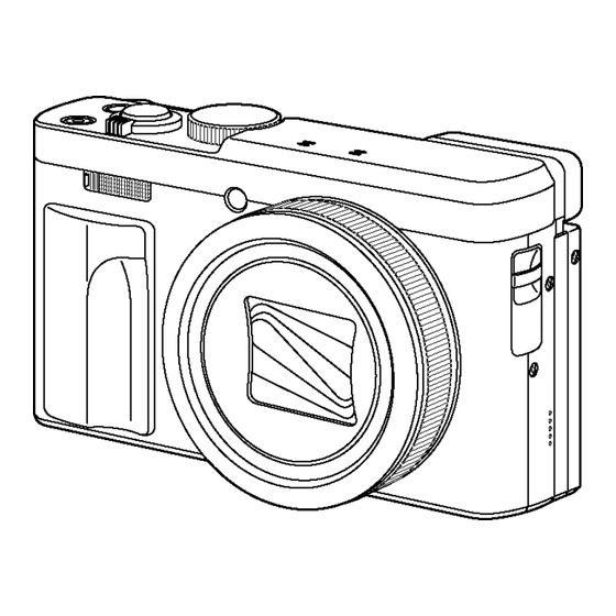
DC-TZ90EB
Model No.
DC-TZ90EF
DC-TZ90EG
DC-TZ90EP
DC-TZ90GA
DC-TZ90GC
DC-TZ90GN
DC-TZ91EG
DC-TZ92EF
DC-TZ93EB
DC-ZS70P
DC-ZS70PP
DC-ZS70GH
DC-ZS70GK
DC-ZS70GT
Colours
Product Color
(S)....................Silver Type
(K)....................Black Type
© Panasonic Corporation 2017.
Unauthorized copying and distribution is a violation
of law.
ORDER NO.DSC1706014CE
B26
Digital Camera
Advertisement
Table of Contents


Need help?
Do you have a question about the Lumix DC-TZ90EB and is the answer not in the manual?
Questions and answers