Table of Contents

Advertisement

Dell PowerEdge R660
Installation and Service Manual
Regulatory Model: E83S
Regulatory Type: E83S001
February 2023
Rev. A00

Advertisement

Table of Contents
loading
Need help?

Need help?

Do you have a question about the PowerEdge R660 and is the answer not in the manual?

Questions and answers

Subscribe to Our Youtube Channel

Summary of Contents for Dell PowerEdge R660

  • Page 1 Dell PowerEdge R660 Installation and Service Manual Regulatory Model: E83S Regulatory Type: E83S001 February 2023 Rev. A00...
  • Page 2 A WARNING indicates a potential for property damage, personal injury, or death. © 2023 Dell Inc. or its subsidiaries. All rights reserved. Dell Technologies, Dell, and other trademarks are trademarks of Dell Inc. or its subsidiaries. Other trademarks may be trademarks of their respective owners.
  • Page 3: Table Of Contents

    Contents Chapter 1: About this document....................8 Chapter 2: PowerEdge R660 system overview................9 Front view of the system..............................9 Left control panel view............................... 12 Right control panel view............................. 13 Rear view of the system..............................14 Inside the system ................................19 Locating the Express Service Code and Service Tag....................
  • Page 4 System Setup..................................47 System BIOS.................................48 iDRAC Settings................................68 Device Settings................................68 Service Tag Settings..............................68 Dell Lifecycle Controller..............................68 Embedded system management..........................68 Boot Manager..................................69 PXE boot..................................... 69 Chapter 6: Minimum to POST and system management configuration validation......70 Minimum configuration to POST ..........................70 Configuration validation..............................
  • Page 5 Removing an EDSFF E3.S drive carrier........................ 120 Installing an EDSFF E3.S drive carrier........................121 Removing an EDSFF E3.S drive from the drive carrier..................122 Installing an EDSFF E3.S drive into the drive carrier..................123 Drive backplane................................124 Drive backplane connectors............................ 124 Removing the drive backplane ..........................
  • Page 6 Intrusion switch................................207 Removing the intrusion switch module........................207 Installing the intrusion switch module........................208 M.2 SSD module................................209 Removing the M.2 NVMe SSD module........................209 Installing the M.2 NVMe SSD module........................209 Optional BOSS-N1 module.............................210 Removing the BOSS-N1 module blank........................210 Installing the BOSS-N1 module blank........................211 Removing the BOSS-N1 card carrier blank......................212 Installing the BOSS-N1 card carrier blank......................212 Removing the BOSS-N1 module..........................213...
  • Page 7 Chapter 11: Using system diagnostics..................264 Dell Embedded System Diagnostics........................... 264 Running the Embedded System Diagnostics from Boot Manager..............264 Running the Embedded System Diagnostics from the Dell Lifecycle Controller........264 System diagnostic controls............................ 265 Chapter 12: Getting help......................266 Recycling or End-of-Life service information......................
  • Page 8: Chapter 1: About This Document

    About this document This document provides an overview about the system, information about installing and replacing components, diagnostic tools, and guidelines to be followed while installing certain components. About this document...
  • Page 9: Chapter 2: Poweredge R660 System Overview
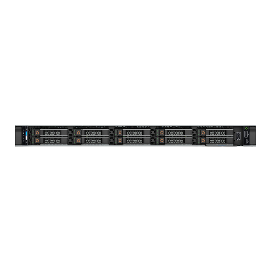
    ● Up to 8 x 2.5-inch or 10 x 2.5-inch SAS or SATA or NVMe (HDD/SSD) drives. 14 x EDSFF E3.S 16 x EDSFF E3.S drives. NOTE: For more information about how to hot swap NVMe PCIe SSD U.2 device, see the Dell Express Flash NVMe PCIe SSD User's Guide at https://www.dell.com/support...
  • Page 10 NOTE: For drive slot numbers, see the System information labels section. Right control panel Contains the power button, VGA port, USB port, iDRAC Direct (Micro-AB USB) port, and the iDRAC Direct status LED. PowerEdge R660 system overview...
  • Page 11 Right control panel Contains the power button, VGA port, USB port, iDRAC Direct (Micro-AB USB) port, and the iDRAC Direct status LED. VGA port Enables you to connect a display device to the system. PowerEdge R660 system overview...
  • Page 12: Left Control Panel View

    Table 5. Left control panel with optional iDRAC Quick Sync 2 indicator  Item Indicator, button, or Icon Description connector Status LED indicators Indicates the status of the system. For more information, see the Status LED indicators section. PowerEdge R660 system overview...
  • Page 13: Right Control Panel View

    You can access system inventory, Dell Lifecycle Controller logs or system logs, system health status, and also configure iDRAC, BIOS, and networking parameters. You can also launch the virtual Keyboard, Video, and Mouse (KVM) viewer and virtual Kernel- based Virtual Machine (KVM), on a supported mobile device.
  • Page 14: Rear View Of The System

    Direct The iDRAC Direct (Micro-AB USB) port enables you to access the iDRAC (Micro-AB USB) direct Micro-AB USB features. For more information, see the Integrated Dell port Remote Access Controller User's Guide at www.dell.com/poweredgemanuals. NOTE: You can configure iDRAC Direct by using a USB to micro USB (type AB) cable, which you can connect to your laptop or tablet.
  • Page 15 Dedicated iDRAC9 Ethernet Enables you to remotely access iDRAC. For more information, port see the Integrated Dell Remote Access Controller User's Guide at www.dell.com/poweredgemanuals. OCP NIC card (optional) The OCP NIC card supports OCP 3.0. The NIC ports are integrated on the OCP card which is connected to the system board.
  • Page 16 Dedicated iDRAC9 Ethernet Enables you to remotely access iDRAC. For more information, port see the Integrated Dell Remote Access Controller User's Guide at www.dell.com/poweredgemanuals. OCP NIC card (optional) The OCP NIC card supports OCP 3.0. The NIC ports are integrated on the OCP card which is connected to the system board.
  • Page 17 Dedicated iDRAC9 Ethernet Enables you to remotely access iDRAC. For more information, port see the Integrated Dell Remote Access Controller User's Guide at www.dell.com/poweredgemanuals. OCP NIC card (optional) The OCP NIC card supports OCP 3.0. The NIC ports are integrated on the OCP card which is connected to the system board.
  • Page 18 Dedicated iDRAC9 Ethernet Enables you to remotely access iDRAC. For more information, port see the Integrated Dell Remote Access Controller User's Guide at www.dell.com/poweredgemanuals. OCP NIC card (optional) The OCP NIC card supports OCP 3.0. The NIC ports are integrated on the OCP card which is connected to the system board.
  • Page 19: Inside The System

    Dedicated iDRAC9 Ethernet Enables you to remotely access iDRAC. For more information, port see the Integrated Dell Remote Access Controller User's Guide at www.dell.com/poweredgemanuals. OCP NIC card (optional) The OCP NIC card supports OCP 3.0. The NIC ports are integrated on the OCP card which is connected to the system board.
  • Page 20: Locating The Express Service Code And Service Tag

    Service Code, Manufacture date, NIC, MAC address, QRL label, and so on. If you have opted for the secure default access to iDRAC, the Information tag also contains the iDRAC secure default password. If you have opted for iDRAC Quick Sync PowerEdge R660 system overview...
  • Page 21: System Information Labels

    4. iDRAC MAC address and iDRAC secure password label 5. Service Tag, Express Service Code, QRL label System information labels The system information labels are located on back side of the system cover. Figure 17. Service information PowerEdge R660 system overview...
  • Page 22 Figure 18. Memory information and system board connectors PowerEdge R660 system overview...
  • Page 23 Figure 19. Electrical overview PowerEdge R660 system overview...
  • Page 24 Figure 20. LED behavior Figure 21. Icon legend Figure 22. Configuration and layout for 2.5-inch drive system PowerEdge R660 system overview...
  • Page 25 Figure 23. System tasks Figure 24. Heat sink Figure 25. BOSS-N1 PowerEdge R660 system overview...
  • Page 26 Figure 26. Express service tag PowerEdge R660 system overview...
  • Page 27: Rail Sizing And Rack Compatibility Matrix

    Rail sizing and rack compatibility matrix For specific information about the rail solutions compatible with your system, see the Dell Enterprise Systems Rail Sizing and Rack Compatibility Matrix available at https://i.dell.com/sites/csdocuments/Business_solutions_engineering- Docs_Documents/en/rail-rack-matrix.pdf. The document provides the information that is listed below: ●...
  • Page 28: Chapter 3: Technical Specifications

    Technical specifications The technical and environmental specifications of your system are outlined in this section. Topics: • Chassis dimensions • System weight • Processor specifications • PSU specifications • Cooling fan specifications • Supported operating systems • System battery specifications •...
  • Page 29: Chassis Dimensions

    Chassis dimensions Figure 27. Chassis dimensions Table 12. PowerEdge R660 chassis dimensions  Drives 10 drives 482.0 mm (18.97 434.0 mm 42.8 mm (1.68 35.84 mm (1.41 751.47 mm 787.04 mm inches) (17.08 inches) inches) inches) With bezel, (29.6 inches) (30.99 inches) 22 mm (0.86 inches)
  • Page 30: Processor Specifications

    Maximum weight (with all drives/SSDs) A server without drives installed 18.5 kg (40.78 lbs) Processor specifications Table 14. PowerEdge R660 processor specifications   Supported processor Number of processors supported Gen Intel® Xeon® Scalable or Intel® Xeon® Max Up to two Processors Table 15.
  • Page 31: Psu Specifications

    PSU specifications The PowerEdge R660 system supports up to two AC or DC power supply units (PSUs). Table 16. PSU specifications   Class Heat Frequency Voltage Current (A) dissipation (Hz) High line Low line (maximum) 200–240 V 100–120 V (BTU/hr)
  • Page 32: Cooling Fan Specifications

    C13 power cord combined with C14 to C15 jumper power cord can be used to adapt 1800 W PSU. Cooling fan specifications The PowerEdge R660 system supports up to four sets of standard (STD) cooling fans or four sets of High performance gold (HPR GOLD) cooling fans.
  • Page 33: System Battery Specifications

    The PowerEdge R660 system uses one CR 2032 3.0-V lithium coin cell battery. Expansion card riser specifications The PowerEdge R660 system supports up to three PCI express (PCIe), (six full length and 10 low profile) slots on the system board.
  • Page 34: Storage Controller Specifications

    ● 14 x EDSFF E3.S, hot-swappable NVMe drives. ● 16 x EDSFF E3.S, hot-swappable NVMe drives. NOTE: For more information about how to hot swap NVMe PCIe SSD U.2 device, see the Dell Express Flash NVMe PCIe SSD User's Guide at https://www.dell.com/support >...
  • Page 35: Serial Connector Specifications

    The micro USB 2.0 compliant port can only be used as an iDRAC Direct or a management port. VGA ports specifications The PowerEdge R660 system supports DB-15 VGA port on front panel and on rear I/O board (optional for Direct Liquid Cooling configuration).
  • Page 36: Environmental Specifications

    1920 x 1200 8, 16, 32 Environmental specifications NOTE: For additional information about environmental certifications, refer to the Product Environmental Datasheet located with the Documentation on www.dell.com/support/home. Table 26. Continuous Operation Specifications for ASHRAE A2  Temperature Specifications Allowable continuous operations Temperature range for altitudes <= 900 m (<=...
  • Page 37: Thermal Restriction Matrix

    Table 29. Common Environmental Specifications for ASHRAE A2, A3, A4   Temperature Specifications Allowable continuous operations Maximum temperature gradient (applies to both 20°C in an hour* (36°F in an hour) and 5°C in 15 minutes (9°F in 15 operation and non-operation) minutes), 5°C in an hour* (9°F in an hour) for tape hardware NOTE: * - Per ASHRAE thermal guidelines for tape hardware, these are...
  • Page 38 Table 34. Thermal restriction matrix for air cooled configuration  8 x 2.5- 10 x 10 x 2.5- 10 x inch 2.5- 10 x 2.5- 16 x 14 x inch 2.5- Configuration Backplan NVMe / inch inch EDSFF EDSFF SAS/ inch SAS/ SAS/ NVMe...
  • Page 39 Table 34. Thermal restriction matrix for air cooled configuration (continued) 8 x 2.5- 10 x 10 x 2.5- 10 x inch 2.5- 10 x 2.5- 16 x 14 x inch 2.5- Configuration Backplan NVMe / inch inch EDSFF EDSFF SAS/ inch SAS/ SAS/ NVMe...
  • Page 40 Table 35. Thermal restriction for memory  8 x 2.5- inch 10x 2.5- 16 x 14 x Configurati 10x 2.5-inch 10 x 2.5- 10 x 2.5- NVMe / inch SAS/ EDSFF EDSFF Backplane SAS/SATA inch NVMe inch NVMe SAS/ SATA E3.S E3.S SATA Rear...
  • Page 41: Thermal Air Restrictions

    ● 2.5 inch NVMe storage are not supported in a 8 x 2.5 inch and 10 x 2.5 inch storage configuration. ● Rear drives are not supported. ● Non Dell qualified peripheral cards and/or peripheral cards greater than 25 W are not supported. ● GPU is not supported.
  • Page 42 ● Two power supplies are required. System performance may be reduced in the event of a PSU failure. ● Non Dell qualified peripheral cards and/or peripheral cards greater than 25 W are not supported. ● OCP 3.0 card is not supported.
  • Page 43: Chapter 4: Initial System Setup And Configuration

    Initial system setup and configuration This section describes the tasks for initial setup and configuration of the Dell system. The section also provides general steps to set up the system and the reference guides for detailed information. Topics: • Setting up the system •...
  • Page 44: Options To Log In To Idrac

    OpenManage Deployment Toolkit Dell OpenManage Deployment Toolkit User's Guide available https://www.dell.com/openmanagemanuals > Open Manage Deployment Toolkit. iDRAC Direct Integrated Dell Remote Access Controller User's Guide at https://www.dell.com/idracmanuals or for system specific Integrated Dell Remote Access Controller User's Guide, go to https://www.dell.com/poweredgemanuals >...
  • Page 45: Resources To Install Operating System

    Ensure that you change the default username and password after setting up the iDRAC IP address. For more information about logging in to the iDRAC and iDRAC licenses, see the latest Integrated Dell Remote Access Controller User's Guide at www.dell.com/idracmanuals.
  • Page 46: Options To Download And Install Os Drivers

    Ensure that you clear the web browser cache before downloading the drivers and firmware. Steps 1. Go to www.dell.com/support/drivers. 2. Enter the Service Tag of the system in the Enter a Dell Service Tag, Dell Product ID or Model field, and then press Enter. NOTE: If you do not have the Service Tag, click Browse all products, and navigate to your product.
  • Page 47: Chapter 5: Pre-Operating System Management Applications

    UEFI (Unified Extensible Firmware Interface). You can enable or disable various iDRAC parameters by using the iDRAC settings utility. For more information about this utility, see Integrated Dell Remote Access Controller User's Guide available at https:// www.dell.com/idracmanuals.
  • Page 48: System Bios

    Table 41. System Setup Main Menu  (continued) Option Description Device Settings Enables you to configure device settings for devices such as storage controllers or network cards. Service Tag Settings Enables you to configure the System Service Tag. System BIOS To view the System BIOS screen, power on the system, press F2, and click System Setup Main Menu > System BIOS. Table 42.
  • Page 49 Specify the FRM percentage by using the Fault Resilient Mode Memory Size[%] feature. When Dell NUMA Fault Resilient Mode (FRM) is enabled, a percentage of the installed memory in every NUMA node is configured to create a fault resilient zone for use by select hypervisors for host virtualization resilience.
  • Page 50 Table 44. Memory Settings details (continued) Option Description mapped out. When set to Enabled it can impact the system performance under certain workloads. This feature is applicable for x4 DIMMs only. This option is set to Enabled by default. Memory training When option is set to Fast and memory configuration is not changed, the system uses previously saved memory training parameters to train the memory subsystems and system boot time is also reduced.
  • Page 51 MADT Core Enumeration Specifies the MADT Core Enumeration. This option is set to default in Round Robin. Linear option supports industry core enumeration whereas, Round Robin option supports Dell optimized core enumeration. UMA Based Clustering It is a read-only field and displays as Quadrant , when Sub NUMA Cluster is disabled or displays as Disabled, when Sub NUMA Cluster is either 2-way or 4-way.
  • Page 52 Enables you to configure the Dell AVX scaling technology. This option is set to 0 by default. Enter the value from 0 to 12 bins. The value that is entered decreases the Dell AVX Scaling Technology frequency when the Dell-controlled Turbo feature is enabled.
  • Page 53 Table 45. Processor Settings details (continued) Option Description uncore power budgeting. This option is set to Enabled by default. Processor Core Speed Specifies the maximum core frequency of the processor. Processor Bus Speed Specifies the bus speed of the processor. NOTE: The processor bus speed option displays only when both processors are installed.
  • Page 54 Enables or disables the boot mode. The option is set to Non-RAID mode by default. BIOS NVMe Driver Sets the drive type to boot the NVMe driver. The available options are Dell Qualified Drives and All Drives. This option is set to Dell Qualified Drives by default.
  • Page 55 Operating systems must be UEFI-compatible to be installed from the UEFI boot mode. DOS and 32-bit operating systems do not support UEFI and can only be installed from the BIOS boot mode. NOTE: For the latest information about supported operating systems, go to www.dell.com/ossupport. Changing boot order About this task You may have to change the boot order if you want to boot from a USB key or an optical drive.
  • Page 56 This field specifies the name of the NVMe-oF host NQN. Allowed input is in the following format: nqn.yyyy-mm.<Reserved Domain Name>:<Unique String>. Leave it empty to use system generated value with following format: nqn.1988-11.com.dell:<Model name>.<Model number>.<Service Tag>. NVMe-oF Host Id This field specifies a 16 bytes value of the NVMe-oF host identifier that uniquely identifies this host with the controller in the NVM subsystem.
  • Page 57 Table 52. Network Settings details (continued) Option Description Host Security Key Path This field specifies the Host security key path. NVMe-oF SubSystem Settings This field controls the parameters for the NVMe-oF subsystem n connections. Table 53. PXE Device n Settings details  Option Description Interface...
  • Page 58 Table 55. ISCSI Device1 Settings screen details  Option Description Connection 1 Enables or disables the iSCSI connection. This option is set to Disabled by default. Connection 2 Enables or disables the iSCSI connection. This option is set to Disabled by default. Connection 1 Settings Enables you to control the configuration for the iSCSI connection.
  • Page 59 Table 58. NVMe-oF SubSystem n Settings (continued) Option Description NVMe-oF subsystem info via DHCP Enables and disables the NVMe-oF subsystem's DHCP for this connection. This option is set to Disabled by default. NVMe-oF subsystem NQN Specifies the NVMe-oF subsystem's NQN for this connection. NVMe-oF subsystem Address Specifies the NVMe-oF subsystem's IP address for this connection.
  • Page 60 Table 59. Integrated Devices details (continued) Option Description during POST and preboot environment. The embedded video will then be disabled right before the operating system boots. This option is set to Enabled by default. NOTE: When there are multiple add-in graphic cards installed in the system, the first card discovered during PCI enumeration is selected as the primary video.
  • Page 61 NOTE: The serial port is optional for the PowerEdge R660 system. The Serial Communication option is applicable only if the serial COM port is installed in the system. Table 60. Serial Communication details  Option Description Serial Communication Enables the serial communication options. Selects serial communication devices (Serial Device 1 and Serial Device 2) in BIOS.
  • Page 62 Table 61. System Profile Settings details  Option Description System Profile Sets the system profile. If you set the System Profile option to a mode other than Performance Per Watt (DAPC), the BIOS automatically sets the rest of the options. You can only change the rest of the options if the mode is set to Custom.
  • Page 63 System Security To view the System Security screen, power on the system, press F2, and click System Setup Main Menu > System BIOS > System Security. Table 62. System Security details  Option Description CPU AES-NI Improves the speed of applications by performing encryption and decryption by using the Advanced Encryption Standard Instruction Set (AES-NI).
  • Page 64 Table 63. TPM 2.0 security information (continued) Option Description The TPM2 Algorithm Selection option supports SHA1, SHA128, SHA256, SHA512 and SM3 by detecting the TPM module. This option is set to SHA1 by default. Table 64. System Security details  Option Description Intel(R) TXT Enables you to set the Intel Trusted Execution Technology (TXT) option.
  • Page 65 Table 64. System Security details (continued) Option Description SMM Security Mitigation Enables or disables the UEFI SMM security mitigation protections. It is set to Disabled by default. Secure Boot Enables Secure Boot, where the BIOS authenticates each pre-boot image by using the certificates in the Secure Boot Policy.
  • Page 66 A message prompts you to reenter the system password. 5. Reenter the system password, and click OK. 6. In the Setup Password field, type your setup password and press Enter or Tab. A message prompts you to reenter the setup password. 7.
  • Page 67 If you do not type the correct password in three attempts, the system displays the following message: Invalid Password! Number of unsuccessful password attempts: <x> System Halted! Must power down. Even after you power off and restart the system, the error message is displayed until the correct password is typed. The following options are exceptions: ●...
  • Page 68: Idrac Settings

    Dell Lifecycle Controller Dell Lifecycle Controller (LC) provides advanced embedded systems management capabilities including system deployment, configuration, update, maintenance, and diagnosis. LC is delivered as part of the iDRAC out-of-band solution and Dell system embedded Unified Extensible Firmware Interface (UEFI) applications.
  • Page 69: Boot Manager

    Launch System Setup Enables you to access System Setup. Launch Lifecycle Controller Exits the Boot Manager and invokes the Dell Lifecycle Controller program. System Utilities Enables you to launch System Utilities menu such as Launch Diagnostics, BIOS update File Explorer, Reboot System.
  • Page 70: Chapter 6: Minimum To Post And System Management Configuration Validation

    Minimum to POST and system management configuration validation This section describes the minimum to POST system requirement and system management configuration validation of the Dell system. Topics: • Minimum configuration to POST • Configuration validation Minimum configuration to POST The components that are listed below are the minimum configuration to POST: ●...
  • Page 71: Error Messages

    Table 68. Configuration validation error (continued) Error Description Possible cause and Example recommendations missing element (cable, risers, etc). Comm Error A configuration element is not responding System management Comm Error: Backplane 2 to iDRAC using the management interface sideband communication while running an inventory check. Unplug AC Power, reseat the element and replace the element if the problem...
  • Page 72: Chapter 7: Installing And Removing System Components

    Installing and removing system components Topics: • Safety instructions • Before working inside your system • After working inside your system • Recommended tools • Cable routing • Optional front bezel • System cover • Drive backplane cover • Air shrouds •...
  • Page 73: Before Working Inside Your System

    Damage due to servicing that is not authorized by Dell is not covered by your warranty. Read and follow the safety instructions that are shipped with your product. NOTE: It is recommended that you always use an antistatic mat and antistatic strap while working on components inside the system.
  • Page 74: Cable Routing

    For information about DC PSU cabling instructions, go to https://www.dell.com/poweredgemanuals > Rack Servers > PowerEdge R660 > Select This Product > Documentation > Manuals and Documents > Cabling instructions for – 48 – 60 V DC power supply. Cable routing Figure 29.
  • Page 75 Table 71. 8 x 2.5 inch (SAS4/SATA) (fPERC12) (continued) Order From SL4_CPU1_PB2 (signal connector on CTRL_DST_PB1 (fPERC input connector) system board) Figure 30. Configuration 1-: 8 x 2.5 inch (SAS/SATA) (fPERC11) NOTE: Follow the sequential order as shown in the table to remove the cables, to install the cables follow the reverse sequential order.
  • Page 76 Figure 31. Configuration 2: 8 x 2.5 inch (NVMe) (fPERC12) NOTE: Follow the sequential order as shown in the table to remove the cables, to install the cables follow the reverse sequential order. Table 73. 8 x 2.5 inch (NVMe) (fPERC12)  Order From SIG_PWR_1 (system board power...
  • Page 77 Figure 32. Configuration 3: 8 x 2.5 inch (NVMe RAID) (fPERC11- H755N) NOTE: Follow the sequential order as shown in the table to remove the cables, to install the cables follow the reverse sequential order. Table 74. 8 x 2.5 inch (NVMe RAID) (fPERC11- H755N)  Order From SIG_PWR_1 (system board power...
  • Page 78 Figure 33. Configuration 4: 8 x 2.5 inch (NVMe) (Min Config) NOTE: Follow the sequential order as shown in the table to remove the cables, to install the cables follow the reverse sequential order. Table 75. 8 x 2.5 inch (NVMe) (Min Config)  Order From SIG_PWR_1 (system board power...
  • Page 79 Figure 34. Configuration 5: 10 x2.5 (NVMe) + 2 x 2.5 (NVMe) NOTE: Follow the sequential order as shown in the table to remove the cables, to install the cables follow the reverse sequential order. Table 76. 10 x2.5 (NVMe) + 2 x 2.5 (NVMe)  Order From SIG_PWR_1 (system board power...
  • Page 80 Figure 35. Configuration 6: 10 x 2.5 inch (NVMe) (2CPU) NOTE: Follow the sequential order as shown in the table to remove the cables, to install the cables follow the reverse sequential order. Table 77. 10 x 2.5 inch (NVMe) (2CPU)  Order From SIG_PWR_1 (system board power...
  • Page 81 Figure 36. Configuration 7: 10 x 2.5 inch (NVMe) (1CPU) NOTE: Follow the sequential order as shown in the table to remove the cables, to install the cables follow the reverse sequential order. Table 78. 10 x 2.5 inch (NVMe) (1CPU)  Order From SIG_PWR_1 (system board power...
  • Page 82 Figure 37. Configuration 8: 10 x 2.5 inch (SAS/SATA) + 2 x 2.5 inch (SAS/SATA) (fPERC12) NOTE: Follow the sequential order as shown in the table to remove the cables, to install the cables follow the reverse sequential order. Table 79. 10 x 2.5 inch (SAS/SATA) + 2 x 2.5 inch (SAS/SATA) (fPERC12)  Order From SIG_PWR_1 (system board power...
  • Page 83 Figure 38. Configuration 9: 10 x 2.5 inch (SAS/SATA w/ 4 Universal) (fPERC12) NOTE: Follow the sequential order as shown in the table to remove the cables, to install the cables follow the reverse sequential order. Table 80. 10 x 2.5 inch (SAS/SATA w/ 4 Universal) (fPERC12)  Order From SIG_PWR_1 (system board power...
  • Page 84 Figure 39. Configuration 10: 10 x 2.5 inch (SAS/SATA) (fPERC 12) NOTE: Follow the sequential order as shown in the table to remove the cables, to install the cables follow the reverse sequential order. Table 81. 10 x 2.5 inch (SAS/SATA) (fPERC 12)  Order From SIG_PWR_1 (system board power...
  • Page 85 Figure 40. Configuration 11: 10 x 2.5 inch (SAS/SATA) (fPERC11) (Min Config) NOTE: Follow the sequential order as shown in the table to remove the cables, to install the cables follow the reverse sequential order. Table 82. 10 x 2.5 inch (SAS/SATA) (fPERC11) (Min Config)   Order From SIG_PWR_1 (system board power...
  • Page 86 Figure 41. Configuration 12: 10 x 2.5 inch (SAS/SATA w/ 4 Universal) (fPERC11) NOTE: Follow the sequential order as shown in the table to remove the cables, to install the cables follow the reverse sequential order. Table 83. 10 x 2.5 inch (SAS/SATA w/ 4 Universal) (fPERC11)  Order From SIG_PWR_1 (system board power...
  • Page 87 Figure 42. Configuration 13: 10 x 2.5 inch (SAS/SATA) (fPERC12) NOTE: Follow the sequential order as shown in the table to remove the cables, to install the cables follow the reverse sequential order. Table 84. 10 x 2.5 inch (SAS/SATA) (fPERC12)  Order From SIG_PWR_1 (system board power...
  • Page 88 Figure 43. Configuration 14: 10 x 2.5 inch (SAS/SATA w/4 Universal) (fPERC12) NOTE: Follow the sequential order as shown in the table to remove the cables, to install the cables follow the reverse sequential order. Table 85. 10 x 2.5 inch (SAS/SATA w/4 Universal) (fPERC12)  Order From SIG_PWR_1 (system board power...
  • Page 89 Figure 44. Configuration 15: 10 x 2.5 inch (SAS/SATA) + 2 x 2.5 inch (SAS/SATA) (fPERC12) NOTE: Follow the sequential order as shown in the table to remove the cables, to install the cables follow the reverse sequential order. Table 86. 10 x 2.5 inch (SAS/SATA) + 2 x 2.5 inch (SAS/SATA) (fPERC12)  Order From SIG_PWR_1 (system board power...
  • Page 90 Figure 45. Configuration 16: 10 x 2.5 inch (SAS/SATA) + 2 x 2.5 inch (SAS/SATA) (fPERC11) NOTE: Follow the sequential order as shown in the table to remove the cables, to install the cables follow the reverse sequential order. Table 87. 10 x 2.5 inch (SAS/SATA) + 2 x 2.5 inch (SAS/SATA) (fPERC11)  Order From SIG_PWR_1 (system board power...
  • Page 91 Figure 46. Configuration 17: No BP (0 configuration) NOTE: Follow the sequential order as shown in the table to remove the cables, to install the cables follow the reverse sequential order. Table 88. No BP (0 configuration)   Order From LFT_CP (left control panel connector) Ear to handle (left control panel connector) RGT_CP (right control panel connector)
  • Page 92 Figure 47. Configuration 18: BOSS-N1 cable NOTE: Follow the sequential order as shown in the table to remove the cables, to install the cables follow the reverse sequential order. Table 89. BOSS-N1 cable   Order From BOSS_PWR (BOSS-N1 power connector BOSS_PWR (BOSS-N1 power connector on BOSS-N1 module) on system board) SL12_PCH_PA6 (BOSS-N1 signal cable on...
  • Page 93 NOTE: Follow the sequential order as shown in the table to remove the cables, to install the cables follow the reverse sequential order. Table 90. 8 x 2.5 inch Universal Smart Flow (2 CPU) (fPERC11)  Order From SIG_PWR_1 (system board power BP_PWR_1 (backplane power connector) connector) SL3_CPU1_PA2 (signal connector on...
  • Page 94 Figure 49. Configuration 20: 8 x 2.5 inch Universal Smart Flow (H965) (2 CPU) (fPERC12) NOTE: Follow the sequential order as shown in the table to remove the cables, to install the cables follow the reverse sequential order. Table 91. 8 x 2.5 inch Universal Smart Flow (H965) (2 CPU) (fPERC12)  Order From SIG_PWR_1 (system board power...
  • Page 95 Figure 50. Configuration 21: 8 x2.5 inch (SAS4/SATA) Smart Flow (1 CPU) (fPERC11) NOTE: Follow the sequential order as shown in the table to remove the cables, to install the cables follow the reverse sequential order. Table 92. 8 x 2.5 inch (SAS4/SATA) Smart Flow (1 CPU) (fPERC11)  Order From SIG_PWR_1 (system board power...
  • Page 96 Figure 51. Configuration 22: 10 x 2.5 inch NVMe + 2 x EDSFF E3.S x 4 NVMe NOTE: Follow the sequential order as shown in the table to remove the cables, to install the cables follow the reverse sequential order. Table 93.
  • Page 97 Figure 52. Configuration 23:14 x EDSFF E3.S (Gen5x4 NVMe), min config NOTE: Follow the sequential order as shown in the table to remove the cables, to install the cables follow the reverse sequential order. Table 94. 14 x EDSFF E3.S (Gen5 x4 NVMe), min config  Order From SIG_PWR_1 (system board power...
  • Page 98 Figure 53. Configuration 24: 14 x EDSFF E3.S + 2 x EDSFF E3.S (Gen5 x 4 NVMe) NOTE: Follow the sequential order as shown in the table to remove the cables, to install the cables follow the reverse sequential order. Table 95.
  • Page 99 Figure 54. Configuration 25: 16 x EDSFF E3.S Dual RAID (NVMe RAID) NOTE: Follow the sequential order as shown in the table to remove the cables, to install the cables follow the reverse sequential order. Table 96. 16 x EDSFF E3.S Dual RAID (NVMe RAID)  Order From SIG_PWR_1 (system board power...
  • Page 100: Optional Front Bezel

    Figure 55. Configuration 27: Dell DPU (Mellanox: 25 Gb, Pensando: 100 Gb or 25 Gb) without power cable NOTE: Follow the sequential order as shown in the table to remove the cables, to install the cables follow the reverse sequential order.
  • Page 101: Installing The Front Bezel

    Figure 56. Removing the front bezel with the LCD panel Next steps Replace the front bezel. Installing the front bezel The procedure to install the front bezel with and without the LCD panel is the same. Prerequisites 1. Follow the safety guidelines listed in the Safety instructions.
  • Page 102: System Cover

    Figure 57. Installing the front bezel with the LCD panel System cover Removing the system cover Prerequisites 1. Follow the safety guidelines listed in the Safety instructions. 2. Power off the system, and any attached peripherals. 3. Disconnect the system from the electrical outlet and peripherals. Steps 1.
  • Page 103: Installing The System Cover

    Figure 58. Removing the system cover Next steps Replace the system cover. Installing the system cover Prerequisites 1. Follow the safety guidelines listed in the Safety instructions. 2. Follow the procedure listed in Before working inside your system. 3. Ensure that all internal cables are connected and routed properly, and no tools or extra parts are left inside the system. Steps 1.
  • Page 104: Drive Backplane Cover

    Figure 59. Installing the system cover Drive backplane cover Removing the drive backplane cover Prerequisites 1. Follow the safety guidelines listed in the Safety instructions. 2. Follow the procedure listed in Before working inside your system. Steps 1. Slide the backplane cover in the direction of the arrows marked on the drive backplane cover. 2.
  • Page 105: Installing The Drive Backplane Cover

    Figure 60. Removing the drive backplane cover Next steps Replace the drive backplane cover. Installing the drive backplane cover Prerequisites 1. Follow the safety guidelines listed in the Safety instructions. 2. Follow the procedure listed in Before working inside your system.
  • Page 106 Figure 61. Installing the drive backplane cover Next steps 1. Follow the procedure listed in After working inside your system. Installing and removing system components...
  • Page 107: Air Shrouds

    Air shrouds Removing the air shrouds Prerequisites CAUTION: Never operate your system with the air shroud removed. The system may get overheated quickly, resulting in shutdown of the system and loss of data. 1. Follow the safety guidelines listed in the Safety instructions.
  • Page 108: Installing The Air Shrouds

    Figure 63. Removing the air shroud from the rear drive module Next steps Replace the air shroud. Installing the air shrouds Prerequisites 1. Follow the safety guidelines listed in the Safety instructions. 2. Follow the procedure listed in Before working inside your system.
  • Page 109 Figure 64. Installing the air shroud 3. For the air shroud on the rear drive module, align the air shroud with the holes on the riser cage and pin. 4. Lower the air shroud into the rear drive module until it is firmly seated. Figure 65.
  • Page 110: Removing The Pch Shroud

    Removing the PCH shroud Prerequisites CAUTION: Never operate your system with the air shroud removed. The system may get overheated quickly, resulting in shutdown of the system and loss of data. 1. Follow the safety guidelines listed in the Safety instructions.
  • Page 111: Cooling Fans

    Figure 67. Installing the PCH shroud Next steps 1. Follow the procedure listed in After working inside your system. Cooling fans Removing a cooling fan module Prerequisites 1. Follow the safety guidelines listed in the Safety instructions. 2. Follow the procedure listed in Before working inside your system.
  • Page 112: Installing A Cooling Fan Module

    Figure 68. Removing a cooling fan module Next steps Replace a cooling fan module. Installing a cooling fan module Prerequisites 1. Follow the safety guidelines listed in the Safety instructions. 2. Follow the procedure listed in Before working inside your system.
  • Page 113: Drives

    Figure 69. Installing a cooling fan module Next steps 1. If applicable, replace the air shroud. 2. Follow the procedure listed in After working inside your system. Drives Removing a drive blank Prerequisites 1. Follow the safety guidelines listed in the Safety instructions.
  • Page 114: Installing A Drive Blank

    Figure 70. Removing a drive blank Next steps Installing a drive replace the drive blank. Installing a drive blank Prerequisites 1. Follow the safety guidelines listed in the Safety instructions. 2. If installed, remove the front bezel. Steps Insert the drive blank into the drive slot until the release button clicks into place. Figure 71.
  • Page 115: Installing The Drive Carrier

    CAUTION: Before attempting to remove or install a drive while the system is running, see the documentation for the storage controller card to ensure that the host adapter is configured correctly to support drive removal and insertion. CAUTION: To prevent data loss, ensure that your operating system supports drive installation. See the documentation supplied with your operating system.
  • Page 116: Removing The Drive From The Drive Carrier

    1. Follow the safety guidelines listed in the Safety instructions. 2. If installed, remove the front bezel. 3. Remove the drive carrier or remove the drive blank when you want to assemble the drives in to the system. Steps 1. Hold the release handle and slide the drive carrier into the drive slot. 2.
  • Page 117: Installing The Drive Into The Drive Carrier

    Figure 74. Removing the drive from the drive carrier Next steps Install the drive into the drive carrier. Installing the drive into the drive carrier Prerequisites Follow the safety guidelines listed in the Safety instructions NOTE: When installing a drive into the drive carrier, ensure that the screws are torqued to 4 in-lbs. Steps 1.
  • Page 118: Removing An Edsff E3.S Drive Blank

    Figure 75. Installing a drive into the drive carrier Next steps Install the drive carrier. Removing an EDSFF E3.S drive blank Prerequisites 1. Follow the safety guidelines listed in the Safety instructions. 2. If installed, remove the front bezel. CAUTION: To maintain proper system cooling, drive blanks must be installed in all empty drive slots.
  • Page 119: Installing An Edsff E3.S Drive Blank

    Figure 76. Removing an EDSFF E3.S drive blank Next steps Replace the EDSFF E3.S drive blank. Installing an EDSFF E3.S drive blank Prerequisites 1. Follow the safety guidelines listed in the Safety instructions. 2. If installed, remove the front bezel. Steps Slide the drive blank into the drive slot until the release button clicks into place.
  • Page 120: Removing An Edsff E3.S Drive Carrier

    Figure 77. Installing an EDSFF E3.S drive blank Next steps If removed, install the front bezel. Removing an EDSFF E3.S drive carrier Prerequisites 1. Follow the safety guidelines listed in Safety instructions. remove the front bezel. 3. Using the management software, prepare the drive for removal. If the drive is online, the green activity or fault indicator flashes while the drive is turning off.
  • Page 121: Installing An Edsff E3.S Drive Carrier

    Installing an EDSFF E3.S drive carrier Prerequisites CAUTION: Before removing or installing a drive while the system is running, see the www.dell.com/ storagecontrollermanuals documentation for the storage controller card to ensure that the host adapter is configured correctly to support drive removal and insertion.
  • Page 122: Removing An Edsff E3.S Drive From The Drive Carrier

    Figure 79. Installing an EDSFF E3.S drive carrier Next steps install the front bezel. Removing an EDSFF E3.S drive from the drive carrier Prerequisites 1. Follow the safety guidelines listed in the Safety instructions. Remove the drive carrier. Steps 1. Using a Torx 6 screwdriver, remove the screws from the slide rails on the drive carrier. 2.
  • Page 123: Installing An Edsff E3.S Drive Into The Drive Carrier

    Figure 80. Removing an EDSFF E3.S drive from the drive carrier Next steps Install an EDSFF E3.S drive into the drive carrier. Installing an EDSFF E3.S drive into the drive carrier Prerequisites 1. Follow the safety guidelines listed in the Safety instructions.
  • Page 124: Drive Backplane

    Table 98. Supported backplane options  System Supported hard drives options 2.5-inch (x 8) SAS or SATA or NVMe backplane PowerEdge R660 2.5-inch (x10) SAS or SATA or NVMe backplane Figure 82. 8 x 2.5-inch drive backplane 1. DST_PB2 (PCIe/NVMe connector) 2.
  • Page 125: Removing The Drive Backplane

    7. DST_SA1 (PERC to backplane) 8. PWR_CNTRL 9. DST_PA1 (PCIe/NVMe connector) Figure 83. 10 x 2.5-inch drive backplane 1. DST_SB1 2. DST_PA3 (PCIe/NVMe connector) 3. P8 4. DST_PB2 (PCIe/NVMe connector) 5. BP_PWR_1 (backplane power and signal cable to system 6. PWR_CTRL board) 7.
  • Page 126: Installing The Drive Backplane

    NOTE: The procedure to remove the backplane is similar for all backplane configurations. 1. Follow the safety guidelines listed in the Safety instructions. 2. Follow the procedure listed in Before working inside your system. 3. If installed, remove the air shroud.
  • Page 127: Removing The 14 X Edsff E3.S Drive Backplane

    NOTE: To avoid damaging the backplane, ensure to move the control panel cables from the cable routing clips before removing the backplane. NOTE: Route the cables properly when you replace it to prevent the cables from being pinched or crimped. Steps 1.
  • Page 128: Installing The 14 X Edsff E3.S Drive Backplane

    NOTE: The procedure to remove the backplane is similar for all backplane configurations. 1. Follow the safety guidelines listed in the Safety instructions. 2. Follow the procedure listed in Before working inside your system. 3. If installed, remove the air shroud.
  • Page 129: Removing The 16 X Edsff E3.S Drive Backplane

    NOTE: To avoid damaging the backplane, ensure to move the control panel cables from the cable routing clips before removing the backplane. NOTE: Route the cable properly when you replace it to prevent the cable from being pinched or crimped. NOTE: Refer cable routing...
  • Page 130: Installing The 16 X Edsff E3.S Drive Backplane

    3. If installed, remove the air shroud. Remove the drive backplane cover. Remove the drive carrier. 6. Observe and disconnect the drive backplane cables from the connector on the system board and backplane. NOTE: Refer cable routing topic for more information. Steps 1.
  • Page 131: Side Wall Brackets

    NOTE: Route the cable properly when you replace it to prevent the cable from being pinched or crimped. NOTE: Refer cable routing topic for more information. NOTE: To avoid damaging the backplane, ensure to move the control panel cables from the cable routing clips before removing the backplane.
  • Page 132: Removing The Side Wall Bracket

    Table 99. Side and center bracket perfect sealing  Configuration Foam installed on the Foam installed on the left side Foam installed on the center right side bracket bracket bracket No BP (0 drive Installed Installed Installed configuration) chassis 8 x 2.5 inch Installed Installed Installed...
  • Page 133 Steps 1. Lift the side wall bracket from the chassis. 2. Open the side wall cable holder, remove the cables from the side wall cable holder. Figure 93. Removing the left side wall bracket Figure 94. Removing the right side wall bracket Next steps Replace the side wall bracket.
  • Page 134: Installing The Side Wall Bracket

    Installing the side wall bracket Prerequisites 1. Follow the safety guidelines listed in the Safety instructions. 2. Follow the procedure listed in the Before working inside your system. 3. If installed, remove the air shroud. Remove the cooling fan. NOTE: Ensure that you note the routing of the cables as you remove them from the system board.
  • Page 135: Perc Modules

    Figure 96. Installing the right side wall bracket Next steps 1. If removed, replace the air shroud. Replace the cooling fan. 3. Follow the procedure listed in the After working inside your system. PERC modules Removing the front mounting front PERC module Prerequisites 1.
  • Page 136 Figure 97. Removing the front mounting front PERC card 5. Use a Phillips #2 screwdriver, to remove the four screws on the battery PERC shroud. 6. Disconnect the battery power cable from the front PERC card. 7. Remove the battery PERC shroud from the front PERC.card. NOTE: The numbers on the image do not depict the exact steps.
  • Page 137: Installing The Front Mounting Front Perc Module

    Figure 99. Removing the front PERC card from the PERC mounting tray Next steps Replace the front mounting front PERC module. Installing the front mounting front PERC module Prerequisites 1. Follow the safety guidelines listed in the Safety instructions. 2. Follow the procedure listed in Before working inside your system.
  • Page 138 Figure 100. Installing the front PERC card to the PERC mounting tray 3. Align and install the battery PERC shroud on the front PERC.card. 4. Connect the battery power cable to the front PERC card. 5. Using a Phillips #2 screwdriver, replace the four screws to secure the battery PERC shroud to the front PERC card. Figure 101.
  • Page 139: Removing The Rear Mounting Front Perc Module

    Figure 102. Installing the front mounting front PERC card Next steps 1. Reconnect the required cables. 2. If removed, replace the air shroud. Install the drive backplane cover. 4. Follow the procedure listed in After working inside your system. Removing the rear mounting front PERC module Prerequisites 1.
  • Page 140 Figure 103. Removing the rear mounting front PERC module 3. Using a Phillips #2 screwdriver, remove the three screws securing the front PERC module bracket to the drive backplane. 4. Disconnect the battery power cable from the front PERC card. 5.
  • Page 141 Figure 105. Removing the battery from the battery holder 7. Using a Phillips #2 screwdriver, remove the four screws on the front PERC shroud. 8. Remove the front PERC shroud from the PERC.card. 9. Remove the front PERC card from the PERC tray. Figure 106.
  • Page 142: Installing The Rear Mounting Front Perc Module

    Figure 107. Removing the rear mounting front PERC module bracket Next steps Replace the rear mounting front PERC module. Installing the rear mounting front PERC module Prerequisites 1. Follow the safety guidelines listed in the Safety instructions. 2. Follow the procedure listed in the Before working inside your system.
  • Page 143 Figure 108. Installing the rear mounting front PERC module bracket 3. Align and install front PERC card to the guides on the front PERC tray. 4. Align and Install the front PERC shroud on the front PERC card. 5. Using a Phillips #2 screwdriver, tighten the four screws to secure the front PERC shroud to the front PERC card. Figure 109.
  • Page 144 Figure 110. Installing the battery into the battery holder 7. Tilt the battery holder assembly to align the tabs with the front PERC shroud. 8. Press the battery holder assembly on to the front PERC shroud. 9. Connect the battery power cable to the front PERC card. NOTE: Route the battery cable into the front PERC shroud cable holder.
  • Page 145: Removing The Edsff E3.S Perc Module And Battery Tray

    Figure 112. Installing the rear mounting front PERC module Next steps Install the drive backplane. 2. If removed, install the air shroud. Install the drive backplane cover. 4. Follow the procedure listed in After working inside your system. Removing the EDSFF E3.S PERC module and battery tray Prerequisites 1.
  • Page 146 Figure 113. Removing the PERC battery 3. Using a Phillips #2 screwdriver, loosen the captive screw on the PERC battery holder. 4. Remove the PERC battery holder out of the system. NOTE: EDSFF E3.S PERC module can be replaced without removing the battery holder. NOTE: Two batteries can be installed on the battery holder.
  • Page 147 5. Using a Phillips #2 screwdriver, remove the screws on the chassis bracket. 6. Slide and lift the PERC module and drive backplane to disengage from the chassis. Figure 115. Removing the PERC module NOTE: The numbers on the image do not depict the exact steps. The numbers are for representation of sequence. 7.
  • Page 148: Installing Edsff E3.S Perc Module And Battery Tray

    NOTE: The numbers on the image do not depict the exact steps. The numbers are for representation of sequence. Figure 117. Removing the PERC card Next steps Replace the EDSFF E3.S PERC module. Installing EDSFF E3.S PERC module and battery tray Prerequisites 1.
  • Page 149 Figure 118. Installing the H965 PERC module 4. Slide the PERC module until the module is connected to the drive backplane. 5. Using a Phillips #2 screwdriver, tighten the screws on the PERC module. NOTE: The numbers on the image do not depict the exact steps. The numbers are for representation of sequence. Figure 119.
  • Page 150 Figure 120. Installing the PERC battery tray 8. If removed, install battery holder, by placing the PERC battery holder between the E3.S backplanes. 9. Using a Phillips #2 screwdriver, tighten the captive screw on the PERC battery holder. NOTE: The numbers on the image do not depict the exact steps. The numbers are for representation of sequence. Figure 121.
  • Page 151: Rear Drive Module

    NOTE: The numbers on the image do not depict the exact steps. The numbers are for representation of sequence. Figure 122. Installing the PERC battery Next steps 1. If removed, install the air shroud. Install the drive backplane cover. 3. Follow the procedure listed in After working inside your system.
  • Page 152: Installing The Rear Drive Module

    Figure 123. Removing the rear drive module Next steps Replace the rear drive module. Installing the rear drive module Prerequisites 1. Follow the safety guidelines listed in the Safety instructions. 2. Follow the procedure listed in Before working inside your system.
  • Page 153: System Memory

    System memory System memory guidelines The PowerEdge R660 system supports DDR5 registered DIMMs (RDIMMs). Your system memory is organized into eight channels per processor (two memory sockets per channel), 16 memory sockets per processor and 32 memory sockets per system.
  • Page 154 Figure 125. Memory channels Memory channels are organized as follows: Table 100. Memory channels  Processor Channel Channel B Channel C Channel D Channel E Channel F Channel G Channel H Processor Slots A1 Slots A7 Slots A3 Slots A5 and Slots A4 and Slots A6 Slots A2 and...
  • Page 155: General Memory Module Installation Guidelines

    Table 101. Supported memory matrix (continued) DIMM type Rank Capacity DIMM rated Operating Speed voltage and 1 DIMM per 2 DIMMs per speed channel (DPC) channel (DPC) 128 GB DDR5 (1.1 V), 4800 4800 MT/s 4400 MT/s MT/s 256 GB DDR5 (1.1 V), 4800 4800 MT/s 4400 MT/s MT/s...
  • Page 156: Removing A Memory Module

    Table 102. Memory population rules  Processor Memory population Memory population information Single processor A{1}, A{2}, A{3}, A{4}, A{5}, A{6}, 1, 2, 4, 6, 8, 12 or 16 DIMMs are A{7}, A{8}, A{9}, A{10}, A{11}, A{12}, allowed. A{13}, A{14}, A{15}, A{16} Dual processor (Start with processor1.
  • Page 157: Installing A Memory Module

    Figure 126. Removing a memory module Next steps Replace the memory module. 2. If you are removing the memory module permanently, install a memory module blank if TDP >=250W. The procedure to install a memory module blank is similar to that of the memory module. NOTE: When operating your system with single processor, install memory module blanks in processor 2 memory sockets if TDP >=250W.
  • Page 158: Processor And Heat Sink Module

    NOTE: The memory module socket has an alignment key that enables you to install the memory module in the socket in only one orientation. CAUTION: Do not apply pressure at the center of the memory module; apply pressure at both ends of the memory module evenly.
  • Page 159 NOTE: The heat sink and processor are hot to touch for some time after the system has been powered down. Allow the processor heat sink module (PHM) to cool down before handling them. Steps 1. Ensure all four anti-tilt wires are in the locked position (outward position), and then using a Torx T30 screwdriver, loosen the captive nuts on the processor heat sink module (PHM) in the order that is mentioned below: a.
  • Page 160: Removing The Processor From The Processor Heat Sink Module

    Figure 129. Removing a heat sink Next steps If you are removing a faulty heat sink, replace the heat sink, if not, remove the processor. Removing the processor from the processor heat sink module Prerequisites WARNING: Remove the processor from processor and heat sink module (PHM) only if you are replacing the processor or heat sink.
  • Page 161 Figure 130. Removing the processor Figure 131. Removing the Xeon Max processor NOTE: Ensure to return the TIM break lever back to original position. 4. Using your thumb and index finger, first hold the retaining clip release tab at the pin 1 connector, pull out the tip of the retaining clip release tab, and then lift the retaining clip partially from the heat sink.
  • Page 162: Installing The Processor

    Figure 132. Removing the retaining clip Figure 133. Removing the Xeon Max retaining clip Next steps Replace the processor into a processor and heat sink module (PHM). Installing the processor Prerequisites 1. Follow the safety guidelines listed in the Safety instructions.
  • Page 163 Steps 1. Place the processor in the processor tray. NOTE: Ensure the pin 1 indicator on the processor tray is aligned with the pin 1 indicator on the processor. 2. Place the retaining clip on top of the processor in the processor tray aligning pin 1 indicator on the processor. NOTE: Ensure the pin 1 indicator on the retaining clip is aligned with the pin 1 indicator on the processor before placing the retaining clip on the processor.
  • Page 164 Figure 135. Installing the Xeon Max retaining clip 3. Align the processor with retaining clip, by using your fingers press the retaining clip on all the four sides until it clicks into place. NOTE: Ensure that the processor is securely latched to the retaining clip. Figure 136.
  • Page 165 CAUTION: Applying too much thermal grease can result in excess grease coming in contact with and contaminating the processor socket. NOTE: The thermal grease syringe is intended for single use only. Dispose the syringe after you use it. Figure 137. Applying thermal grease 6.
  • Page 166 ● Ensure latching features on retaining clip, and heat sink are aligned during assembly. ● Ensure that the pin 1 indicator on the heat sink is aligned with the pin 1 indicator on the retaining clip before placing the heat sink onto the retaining clip. Figure 139.
  • Page 167: Installing The Processor Heat Sink Module

    Figure 140. Installing the heat sink onto the Xeon Max processor Next steps Replace the processor into a processor and heat sink module (PHM). 2. If removed, Replace the air shroud. 3. Follow the procedure listed in After working inside your system.
  • Page 168 Figure 141. Installing the processor heat sink 3. Set the anti-tilt wires to the locked position (outward position), and then using the Torx T30 screwdriver, tighten the nuts (8 in-lbf) on the PHM: a. In a random order, tighten the first nut three turns. b.
  • Page 169: Removing The Direct Liquid Cooling Module

    Figure 142. Set the anti-tilt wires to the locked position and tightening the nuts Next steps 1. If removed, replace the air shroud. 2. Follow the procedure listed in the After working inside your system. Removing the Direct Liquid Cooling module Prerequisites 1.
  • Page 170: Removing The Processor

    NOTE: Ensure that the anti-tilt wires on the DLC module are in locked position when loosening the captive nuts. 7. Set the anti-tilt wires on the DLC module to the unlock position and lift the DLC module from the system. NOTE: The numbers on the image do not depict the exact steps.
  • Page 171 Steps 1. Place the DLC module with the processor side facing up. 2. Using your thumb, lift the thermal interface material (TIM) break lever to release the processor from the TIM and retaining clip. 3. Holding the processor by the edges, lift the processor away from the retaining clip. NOTE: Ensure to hold the retaining clip to the heat sink as you lift the TIM break lever.
  • Page 172: Installing The Processor

    Figure 145. Removing the retaining clip Next steps Replace the processor. Installing the processor Prerequisites 1. Follow the safety guidelines listed in the Safety instructions. 2. Follow the procedure listed in Before working inside your system. Remove the air shroud. Remove the Direct Liquid Cooling module.
  • Page 173 Figure 146. Installing the retaining clip 3. Align the processor with retaining clip, by using the fingers press the retaining clip on all the four sides until it clicks into place. NOTE: Ensure that the processor is securely latched to the retaining clip. Figure 147.
  • Page 174 CAUTION: Applying too much thermal grease can result in excess grease coming in contact with and contaminating the processor socket. NOTE: The thermal grease syringe is intended for single use only. Dispose the syringe after you use it. Figure 148. Applying thermal grease 6.
  • Page 175: Installing The Direct Liquid Cooling Module

    NOTE: ● Ensure latching features on retaining clip, and DLC module are aligned during assembly. ● Ensure that the pin 1 indicator on the DLC module is aligned with the pin 1 indicator on the retaining clip before placing the DLC module onto the retaining clip. Figure 150.
  • Page 176 NOTE: Ensure that the DLC tubes and liquid cooling leak detection cable are placed towards the rear of the system. 2. Place the module on the processor slot and set all the anti-tilt wires to locked position (outward position). 3. Route the DLC tubes to the front of the system and along the DIMM latches. 4.
  • Page 177: Expansion Cards And Expansion Card Risers

    When an expansion card is not supported or missing, the iDRAC and Lifecycle Controller logs an event. This does not prevent your system from booting. However, if a F1/F2 pause occurs with an error message, see Troubleshooting expansion cards section in the PowerEdge Servers Troubleshooting Guide at www.dell.com/poweredgemanuals. Expansion card installation guidelines Figure 152.
  • Page 178 Figure 153. Riser 1P 1. Slot 1 Figure 154. Riser 2A 1. Slot 1 2. Slot 2 Installing and removing system components...
  • Page 179 Figure 155. Riser 2P 1. Slot 1 2. Slot 2 Figure 156. Riser 2Q 1. Slot 1 2. Slot 2 Installing and removing system components...
  • Page 180 Figure 157. Riser 2R 1. Slot 1 2. Slot 2 Figure 158. Riser 2S 1. Slot 1 Installing and removing system components...
  • Page 181 Figure 159. Riser 3A 1. Slot 3 Figure 160. Riser 3P 1. Slot 3 Installing and removing system components...
  • Page 182 Figure 161. Riser 3Q 1. Slot 3 Figure 162. Riser 3R 1. Slot 3 Installing and removing system components...
  • Page 183 Figure 163. Riser 3S 1. Slot 3 Figure 164. Riser 4P 1. Slot 2 NOTE: The expansion-card slots are not hot-swappable. The following table provides guidelines for installing expansion cards to ensure proper cooling and mechanical fit. The expansion cards with the highest priority should be installed first using the slot priority indicated. All the other expansion cards should be installed in the card priority and slot priority order.
  • Page 184 Table 104. Expansion card riser configurations (continued) Configurations Expansion card PCIe Slots Form factor Controlling Slot's electrical risers processor bandwidth/physical connector Config 2. 3 x LP (2x LP Low Profile Processor 1 PCIe Gen5 x16 (x16 Gen5 + 1x LP Gen4) connector) Low Profile Processor 2...
  • Page 185 Table 105. Configuration 0: No risers (continued) Card type Slot priority Maximum number of cards Broadcom (OCP: 10Gb) Integrated slot Broadcom (OCP: 1Gb) Integrated slot Intel (OCP: 1Gb) Integrated slot Foxconn (BOSS) Integrated slot FOXCONN (Front PERC12) Integrated slot FOXCONN (Front PERC11) Integrated slot Table 106.
  • Page 186 Table 106. Configuration 1. R2A+R3A (continued) Card type Slot priority Maximum number of cards Qlogic (Marvell) (HBA: FC32) 2, 1, 3 Broadcom (NIC: 25Gb) 2, 1, 3 Broadcom (NIC: 10Gb) 2, 1, 3 Intel (NIC: 10Gb) 2, 1, 3 Intel (NIC: 1Gb) 2, 1, 3 Broadcom (NIC: 1Gb) 2, 1, 3...
  • Page 187 Table 107. Configuration 2. R2P+R3P (continued) Card type Slot priority Maximum number of cards Broadcom (HBA: FC64) 2, 1, 3 Broadcom (HBA: FC32) 2, 1, 3 Qlogic (Marvell) (HBA: FC32) 2, 1, 3 Broadcom (NIC: 25Gb) 2, 1, 3 Broadcom (NIC: 10Gb) 2, 1, 3 Intel (NIC: 10Gb) 2, 1, 3...
  • Page 188 Table 108. Configuration 3. R1P+R4P (continued) Card type Slot priority Maximum number of cards Broadcom (NIC: 100Gb) 1, 2 Intel (NIC: 100Gb) 1, 2 Intel (NIC: 25Gb) 1, 2 Broadcom (NIC: 25Gb) 1, 2 Mellanox (NIC: 25Gb) 1, 2 Broadcom (HBA: FC64) 1, 2 Broadcom (HBA: FC32) 1, 2...
  • Page 189 Table 109. Configuration 4. R2R+R3R (continued) Card type Slot priority Maximum number of cards Intel (NIC: 25Gb) 3, 2, 1 Broadcom (HBA: FC64) 3, 2, 1 Broadcom (HBA: FC32) 3, 2, 1 Qlogic (Marvell) (HBA: FC32) 3, 2, 1 Broadcom (NIC: 25Gb) 3, 2, 1 Broadcom (NIC: 10Gb) 3, 2, 1...
  • Page 190 Table 110. Configuration 5. R2A+R3Q (continued) Card type Slot priority Maximum number of cards Intel (NIC: 25Gb) 2, 1 Broadcom (HBA: FC64) 2, 1 Broadcom (HBA: FC32) 2, 1 Qlogic (Marvell) (HBA: FC32) 2, 1 Broadcom (NIC: 25Gb) 2, 1 Broadcom (NIC: 10Gb) 2, 1 Intel (NIC: 10Gb) 2, 1...
  • Page 191 Table 111. Configuration 6-1. R2Q (non-A2, L4) (continued) Card type Slot priority Maximum number of cards Broadcom (HBA: FC32) 2, 1 Qlogic (Marvell) (HBA: FC32) 2, 1 Broadcom (NIC: 25Gb) 2, 1 Broadcom (NIC: 10Gb) 2, 1 Intel (NIC: 10Gb) 2, 1 Intel (NIC: 1Gb) 2, 1 Broadcom (NIC: 1Gb)
  • Page 192 Table 113. Configuration 7. R3P (continued) Card type Slot priority Maximum number of cards Broadcom (OCP: 10Gb) Integrated slot Broadcom (OCP: 1Gb) Integrated slot Intel (OCP: 1Gb) Integrated slot Foxconn (BOSS) Integrated slot FOXCONN (Front PERC12) Integrated slot FOXCONN (Front PERC11) Integrated slot Nvidia (GPU) Intel (GPU)
  • Page 193 Table 114. Configuration 8. R2A (continued) Card type Slot priority Maximum number of cards Broadcom (OCP: 1Gb) Integrated slot Intel (OCP: 1Gb) Integrated slot Foxconn (BOSS) Integrated slot FOXCONN (Front PERC11) Integrated slot Nvidia (GPU) Intel (GPU) Mellanox (NIC: NDR200) Mellanox (NIC: HDR100 VPI) Mellanox (NIC: HDR VPI) Mellanox (NIC: 100Gb) Broadcom (NIC: 100Gb)
  • Page 194: Removing The Expansion Card Risers

    Table 115. Configuration 9. R2S+R3S (continued) Card type Slot priority Maximum number of cards Broadcom (OCP: 1Gb) Integrated slot Intel (OCP: 1Gb) Integrated slot Foxconn (BOSS) Integrated slot Intel (GPU) 1, 3 Mellanox (NIC: NDR200) 1, 3 Mellanox (NIC: NDR400) 1, 3 Mellanox (NIC: HDR100 VPI) 1, 3 Mellanox (NIC: HDR VPI)
  • Page 195 Figure 165. Removing the expansion card riser (Riser 1) 2. For Riser 2 and Direct Liquid Cooling Riser 2, press the blue button on the riser, and holding the touch points lift the expansion card riser from the riser connector on the system board. NOTE: The numbers on the image do not depict the exact steps.
  • Page 196: Installing The Expansion Card Risers

    Figure 167. Removing the expansion card riser (Riser 3) 4. For Riser 4, press the blue tab on the riser, and holding the touch point lift the expansion card riser from the riser connector on the system board. Figure 168. Removing the expansion card riser (Riser 4) Next steps remove the expansion card riser.
  • Page 197 3. If removed, install the expansion cards into the expansion card risers. Steps 1. Holding the edges or the touch points, align the holes on the expansion card riser with the guides on the system board. 2. Lower the expansion card riser into place and press the touch points until the expansion card riser connector is fully seated on the system board connector.
  • Page 198: Removing Expansion Card From The Expansion Card Riser

    Figure 171. Installing the expansion card riser (Riser 3) Figure 172. Installing the expansion card riser (Riser 4) Next steps 1. If required, re-connect the cables to the expansion card. 2. Follow the procedure listed in After working inside your system.
  • Page 199 Steps 1. Pull and lift the expansion card retention latch lock to open. NOTE: Pull the card holder before removing the card from the riser. 2. Hold the expansion card by the edges and pull the card until the card edge connector disengages from the expansion card connector on the riser.
  • Page 200 Figure 175. Installing the filler bracket Next steps 1. If applicable, install an expansion card into the expansion card riser. Installing and removing system components...
  • Page 201: Installing An Expansion Card Into The Expansion Card Riser

    For instructions, see the documentation accompanying the card. CAUTION: Do not install GPUs, network cards, or other PCIe devices on your system that are not validated and tested by Dell. Damage caused by unauthorized and invalidated hardware installation will null and void the system warranty. Steps 1.
  • Page 202 Figure 176. Removing the filler bracket 3. Hold the card by its edges, and align the card edge connector with the expansion card connector on the riser. 4. Insert the card edge connector firmly into the expansion card connector until the card is fully seated. 5.
  • Page 203: Removing The A2 Blank From The Expansion Card Riser

    Figure 178. Installing expansion card into the expansion card riser NOTE: Push the card holder to hold the full length card in the riser. Next steps 1. If applicable, connect the cables to the expansion card. 2. Follow the procedure listed in After working inside your system.
  • Page 204: Installing The A2 Blank On To The Expansion Card Riser

    Figure 179. Removing the A2 blank Next steps Replace the A2 blank on the expansion card riser. Installing the A2 Blank on to the expansion card riser Prerequisites 1. Follow the safety guidelines listed in the Safety instructions. 2. Follow the procedure listed in Before working inside your system.
  • Page 205: Removing The Vga Port

    Figure 180. Installing the A2 blank Next steps Replace the expansion card riser 2. If applicable, replace the air shroud. 3. Follow the procedure listed in After working inside your system. Removing the VGA port Prerequisites 1. Follow the safety guidelines listed in theSafety instructions 2.
  • Page 206: Installing The Vga Port

    Figure 181. Disconnecting the VGA port cable 3. Install the filler bracket if not replacing the VGA port. Next steps Replace the VGA port. Installing the VGA port Prerequisites Before working inside your system Steps 1. Open the latch on the expansion card riser and remove the filler bracket from the expansion card riser. 2.
  • Page 207: Intrusion Switch

    Next steps 1. Follow the procedure listed in After working inside your system. Intrusion switch This is a service technician replaceable part only. Removing the intrusion switch module Prerequisites 1. Follow the safety guidelines listed in the Safety instructions. 2. Follow the procedure listed in Before working inside your system.
  • Page 208: Installing The Intrusion Switch Module

    Installing the intrusion switch module Prerequisites 1. Follow the safety guidelines listed in the Safety instructions. 2. Follow the procedure listed in Before working inside your system. Remove the expansion card riser. NOTE: Ensure that you note the routing of the cables as you remove them from the system board. Route the cables properly when you replace it to prevent the cables from being pinched or crimped.
  • Page 209: M.2 Ssd Module

    M.2 SSD module Removing the M.2 NVMe SSD module Prerequisites 1. Follow the safety guidelines listed in the Safety instructions. 2. Follow the procedure listed in the Before working inside your system. 3. Remove the BOSS-N1 module. Steps 1. Using the Phillips #1 screwdriver, remove the M3 x 0.5 x 4.5 mm screw securing the M.2 NVMe SSD module to the BOSS-N1 card.
  • Page 210: Optional Boss-N1 Module

    Figure 186. Installing the M.2 NVMe SSD module Next steps 1. Install the BOSS_N1 module. 2. Follow the procedure listed in the After working inside your system. Optional BOSS-N1 module Removing the BOSS-N1 module blank Prerequisites Follow the safety guidelines listed in the Safety instructions.
  • Page 211: Installing The Boss-N1 Module Blank

    Figure 187. Removing the BOSS-N1 module blank Next steps Replace the BOSS-N1 module blank install BOSS-N1 module. Installing the BOSS-N1 module blank Prerequisites 1. Follow the safety guidelines listed in the Safety instructions. Steps 1. Align the blank with the BOSS-N1 module bay and push it into the bay until it clicks into place. 2.
  • Page 212: Removing The Boss-N1 Card Carrier Blank

    Removing the BOSS-N1 card carrier blank Prerequisites Follow the safety guidelines listed in the Safety instructions. Steps Press and pull the BOSS-N1 card carrier blank out from the BOSS-N1 module. Figure 189. Removing the BOSS-N1 card carrier blank Next steps Replace the BOSS-N1 card carrier blank install BOSS-N1 card carrier.
  • Page 213: Removing The Boss-N1 Module

    Figure 190. Installing the BOSS-N1 card carrier blank Removing the BOSS-N1 module Prerequisites 1. Follow the safety guidelines listed in the Safety instructions. 2. Follow the procedure listed in the Before working inside your system. Steps 1. Pull and lift the BOSS-N1 card carrier retention latch lock to open. 2.
  • Page 214 3. Using the Phillips #1 screwdriver remove the M3 x 0.5 x 4.5 mm screw that secures the M.2 NVMe SSD to the BOSS-N1 card carrier. 4. Slide the M.2 NVMe SSD out from the BOSS-N1 card carrier. Figure 192. Removing the M.2 NVMe SSD 5.
  • Page 215 10. Remove the power cable from the BOSS-N1 module. Figure 194. Removing the BOSS-N1 power and signal cable from the BOSS-N1 module NOTE: The numbers on the image do not depict the exact steps. The numbers are for representation of sequence. 11.
  • Page 216: Installing The Boss-N1 Module

    Installing the BOSS-N1 module Prerequisites 1. Follow the safety guidelines listed in the Safety instructions. 2. Follow the procedure listed in the Before working inside your system. 3. If installed, remove the BOSS module blank. Steps 1. Slide the BOSS-N1 cover on the BOSS-N1 controller card module. Using the Phillips #1 screwdriver, secure the BOSS-N1 cover on the BOSS-N1 controller card module with the M3 x 0.5 x 4.5 mm screw.
  • Page 217 Figure 197. Connecting the BOSS-N1 power and signal cables to the BOSS-N1 module 3. Align the BOSS-N1 module at an angle with the controller card module slot. 4. Insert the BOSS-N1 module and push the module horizontally towards the rear of the system until firmly seated. 5.
  • Page 218 Figure 199. Installing the M.2 NVMe SSD 10. Slide the BOSS-N1 card carrier into the BOSS-N1 module slot. 11. Close the BOSS-N1 card carrier release latch to lock the carrier in place. Figure 200. Installing the BOSS-N1card carrier NOTE: The numbers on the image do not depict the exact steps. The numbers are for representation of sequence. Next steps 1.
  • Page 219: System Battery

    System battery This is a service technician replaceable part only. Replacing the system battery Prerequisites WARNING: There is a danger of a new battery exploding if it is incorrectly installed. Replace the battery only with the same or equivalent type That is recommended by the manufacturer. Discard used batteries according to the manufacturer's instructions.
  • Page 220: Optional Ocp Card

    Figure 202. Installing the system battery Next steps install the expansion card riser. 2. If applicable, connect the cables to one or more expansion cards. 3. Follow the procedure listed in After working inside your system. 4. Confirm that the battery is operating properly, by performing the following steps: a.
  • Page 221: Installing The Ocp Card

    Remove the expansion card riser CAUTION: Do not install GPUs, network cards, or other PCIe devices on your system that are not validated and tested by Dell. Damage caused by unauthorized and invalidated hardware installation will null and void the system warranty. Steps 1.
  • Page 222: Optional Internal Usb Card

    Figure 204. Installing the OCP card Next steps Install the expansion card riser 2. Follow the procedure listed in After working inside your system. Optional internal USB card NOTE: To locate the internal USB port on the system board, see the System board jumpers and connectors section.
  • Page 223: Installing The Optional Internal Usb Card

    Figure 205. Removing the internal USB card Next steps Replace the internal USB card. Installing the optional internal USB card Prerequisites 1. Follow the safety guidelines listed in the Safety instructions. 2. Follow the procedure listed in Before working inside your system.
  • Page 224: Vga Module

    Figure 206. Installing the internal USB card Next steps 1. Follow the procedure listed in After working inside your system. 2. While booting, press F2 to enter System Setup and verify that the system detects the USB memory key. VGA module This is a service technician replaceable part only.
  • Page 225: Installing The Vga Module

    NOTE: The numbers on the image do not depict the exact steps. The numbers are for representation of sequence. Figure 207. Removing the VGA module Next steps Replace the VGA module. Installing the VGA module Prerequisites 1. Follow the safety guidelines listed in the Safety instructions.
  • Page 226: Power Supply Unit

    For information about DC PSU cabling instructions, go to https://www.dell.com/poweredgemanuals > Rack Servers > PowerEdge R660 > Select This Product > Documentation > Manuals and Documents > Cabling instructions for – 48 – 60 V DC power supply. Hot spare feature Your system supports the hot spare feature that significantly reduces the power overhead associated with the power supply unit (PSU) redundancy.
  • Page 227: Removing A Power Supply Unit Blank

    ● If the load on the active PSU falls below 20 percent of PSU rated power wattage, then the redundant PSU is switched to the sleep state. You can configure the hot spare feature by using the iDRAC settings. For more information, see the iDRAC User’s Guide available at www.dell.com/poweredgemanuals. Removing a power supply unit blank Prerequisites...
  • Page 228: Removing A Power Supply Unit

    3. Remove the cable from the strap on the PSU handle. 4. Unlatch and lift the optional cable management arm if it interferes with the PSU removal. For information about the cable management arm, see the system’s rack documentation at https://www.dell.com/ poweredgemanuals Steps Press the release latch, and holding the PSU handle slide the PSU out of the PSU bay.
  • Page 229: Installing A Power Supply Unit

    While replacing the hot swappable PSU, after next server boot; the new PSU automatically updates to the same firmware and configuration of the replaced one. For updating to the latest firmware and changing the configuration, see the Lifecycle Controller User's Guide at https://www.dell.com/idracmanuals. Installing and removing system components...
  • Page 230: Optional Serial Com Port

    Optional serial COM port This is a service technician replaceable part only. Removing the serial COM port Prerequisites 1. Follow the safety guidelines listed in the Safety instructions. 2. Follow the procedure listed in Before working inside your system. Steps 1.
  • Page 231: Installing The Serial Com Port

    Figure 214. Installing the filler bracket Next steps Replace the serial COM port. Installing the serial COM port Prerequisites 1. Follow the safety guidelines listed in the Safety instructions. 2. Follow the procedure listed in Before working inside your system. Lift the expansion card riser and disconnect the serial COM port cable from the connector on the rear I/O board.
  • Page 232 Figure 215. Removing the filler bracket 2. Slide the serial COM port into the expansion card riser. 3. Connect the serial COM port cable to the serial port. 4. Close the expansion card retention latch. 5. Connect the serial COM port cable to the connector on the rear I/O board. NOTE: The numbers on the image do not depict the exact steps.
  • Page 233: System Board

    System board This is a service technician replaceable part only. Removing the system board Prerequisites CAUTION: If you are using the Trusted Platform Module (TPM) with an encryption key, you may be prompted to create a recovery key during program or System Setup. Be sure to create and safely store this recovery key. If you replace this system board, you must supply the recovery key when you restart your system or program before you can access the encrypted data on your drives.
  • Page 234: Installing The System Board

    Figure 217. Removing the system board Next steps Install the system board. Installing the system board Prerequisites NOTE: Before replacing the system board, replace the old iDRAC MAC address label on the Information tag with the iDRAC MAC address label of the replacement system board 1.
  • Page 235 4. If you are not using Easy Restore, import your new or existing iDRAC Enterprise license. For more information, see the Integrated Dell Remote Access Controller User's Guide available at https://www.dell.com/idracmanuals. 5. Follow the procedure listed in After working inside your system.
  • Page 236: Restoring The System Using Easy Restore

    Restoring the system using Easy Restore The Easy Restore feature enables you to restore your service tag, license, UEFI configuration, and the system configuration data after replacing the system board. All data is backed up in a backup flash device automatically. If BIOS detects a new system board, and the service tag in the backup flash device, BIOS prompts the user to restore the backup information.
  • Page 237 Steps 1. Using a Phillips # 2 screwdriver, remove the screws that secure the LAN on Motherboard (LOM) card, Management Interface card (MIC), and rear I/O board to the system board. 2. Holding the edges, pull the LOM card, MIC card, or rear I/O board to disconnect from the connector on the system board. Figure 219.
  • Page 238: Installing The Lom Card (Optional),Mic Card, And Rear I/O Board

    Figure 221. Removing the MIC card NOTE: MIC is card is only available in the system that supports Dell DPU cards. Next steps Replace the LOM card and rear I/O board. Installing the LOM card (optional),MIC card, and rear I/O board Prerequisites 1.
  • Page 239 Figure 222. Installing the LOM card and rear I/O board Figure 223. Installing the LOM card and Liquid cooling rear I/O board Installing and removing system components...
  • Page 240: Control Panel

    Figure 224. Installing the MIC card NOTE: MIC is card is only available in the system that supports Dell DPU cards. Next steps Install the system board. 2. Follow the procedure listed in After working inside your system. Control panel This is a service technician replaceable part only.
  • Page 241: Installing The Right Control Panel

    Figure 225. Removing the right control panel Next steps Replace the right control panel. Installing the right control panel Prerequisites 1. Follow the safety guidelines listed in the Safety instructions. 2. Follow the procedure listed in Before working inside your system.
  • Page 242: Removing The Left Control Panel

    Figure 226. Installing the right control panel Next steps Install the drive backplane cover. 2. If applicable, replace the air shroud. 3. Follow the procedure listed in After working inside your system. Removing the left control panel Prerequisites 1. Follow the safety guidelines listed in the Safety instructions.
  • Page 243: Installing The Left Control Panel

    Figure 227. Removing the left control panel Next steps Replace the left control panel. Installing the left control panel Prerequisites 1. Follow the safety guidelines listed in the Safety instructions. 2. Follow the procedure listed in Before working inside your system.
  • Page 244: Trusted Platform Module

    Figure 228. Installing the left control panel Next steps Install the drive backplane cover. 2. If applicable, replace the air shroud. 3. Follow the procedure listed in After working inside your system. Trusted Platform Module This is a service technician replaceable part only. Upgrading the Trusted Platform Module Removing the TPM Prerequisites...
  • Page 245: Initializing Tpm For Users

    2. Press to hold the module down and remove the screw using the security Torx 8-bit shipped with the TPM module. 3. Slide the TPM module out from its connector. 4. Push the plastic rivet away from the TPM connector and rotate it 90° counterclockwise to release it from the system board. 5.
  • Page 246: Chapter 8: Upgrade Kits

    Installing a processor heat sink module Direct Liquid Cooling Module Risers Not available as APOS kits, upgrades offered only with the "Basic Deployment Upgrade of Dell Server" service Rail Offered, but without special service instructions Cable Management Arm (CMA) Offered, but without special service instructions NOTE: CMA is not supported in Direct Liquid Cooling configuration.
  • Page 247: Boss-N1 Module Kit

    BOSS-N1 module kit The BOSS-N1 module supports up to two M.2 NVMe SSDs. Before you begin the installation or removal process, follow the safety guidelines before working inside the system instructions. Table 117. BOSS-N1 module kit components  Components in kit R660 (quantity) BOSS-N1 controller card module BOSS-N1 card carrier...
  • Page 248: Serial Com Port Kit

    NOTE: Install a BOSS-N1 card carrier blank if you are only using one BOSS-N1 card carrier. NOTE: Refer to cable routing section, configuration 20 for more information on connecting the BOSS cables to system board connectors. NOTE: Installing the BOSS-N1 card carrier does not require the system to be powered off. System shutdown is only required when installing the BOSS-N1 controller card module.
  • Page 249: Internal Usb Card Kit

    Internal USB card kit The internal USB card kit contains one internal USB card. For installation of internal USB card, see internal USB card section. Upgrade Kits...
  • Page 250: Chapter 9: Jumpers And Connectors

    Jumpers and connectors This topic provides some basic and specific information about jumpers and switches. It also describes the connectors on the various boards in the system. Jumpers on the system board help to disable the system and reset the passwords. To install components and cables correctly, you must know the connectors on the system board.
  • Page 251 Table 119. System board jumpers and connectors (continued) Item Connector Description B9, B1, B15, B7, B11, B3, B13, B5 DIMM for CPU 2 channels A, B, C, D SL10_PCH_SA1 SATA Connector IO_RISER2_A (CPU1) and IO_RISER2_B (CPU2) Riser 2 TPM connector OCP NIC 3.0 connector SL13_CPU1_PB7 PCIe connector 13 Battery...
  • Page 252: System Board Jumper Settings

    Damage due to servicing that is not authorized by Dell is not covered by your warranty. Read and follow the safety instructions that are shipped with your product.
  • Page 253 Steps 1. Power off the system and all attached peripherals. Disconnect the system from the electrical outlet, and disconnect the peripherals. Remove the system cover. 3. Move the jumper on the system board from pins 2 and 4 to pins 4 and 6. Replace the system cover.
  • Page 254: Chapter 10: System Diagnostics And Indicator Codes

    System diagnostics and indicator codes The diagnostic indicators on the system front panel display system status during system startup. Topics: • Status LED indicators • System health and system ID indicator codes • iDRAC Quick Sync 2 indicator codes • iDRAC Direct LED indicator codes •...
  • Page 255 Table 121. Status LED indicators and descriptions (continued) Icon Description Condition Corrective action ● Ambient temperature is too high. temperature is out of range or ● External airflow is obstructed. there is a fan failure). If the problem persists, see the Getting help section.
  • Page 256: System Health And System Id Indicator Codes

    For information about the event and error messages generated by the system firmware and agents that monitor system components, go to qrl.dell.com > Look Up > Error Code, type the error code, and then click Look it up.
  • Page 257: Idrac Quick Sync 2 Indicator Codes

    If the problem persists, see the Getting help section. www.dell.com/poweredgemanuals or Dell OpenManage Server Administrator User’s Guide at https://www.dell.com/openmanagemanuals. Solid amber Indicates that the system is in fail-safe Restart the system. If the problem persists, see mode.
  • Page 258: Lcd Panel

    The LCD panel is used to configure or view the iDRAC IP address of the system. For information about the event and error messages generated by the system firmware and agents that monitor system components, go to qrl.dell.com >...
  • Page 259: Viewing Home Screen

    For information about the event and error messages generated by the system firmware and agents that monitor system components, go to qrl.dell.com > Look Up > Error Code, type the error code, and then click Look it up..
  • Page 260: Nic Indicator Codes

    NIC indicator codes Each NIC on the back of the system has indicators that provide information about the activity and link status. The activity LED indicator indicates if data is flowing through the NIC, and the link LED indicator indicates the speed of the connected network. Figure 235.
  • Page 261 Table 129. AC and DC PSU status indicator codes  Power indicator codes Condition Green Indicates that a valid power source is connected to the PSU and the PSU is operational. Blinking amber Indicates an issue with the PSU. Not powered on Indicates that the power is not connected to the PSU.
  • Page 262: Drive Indicator Codes

    Drive indicator codes The LEDs on the drive carrier indicate the state of each drive. Each drive carrier has two LEDs: an activity LED (green) and a status LED (bicolor, green/amber). The activity LED blinks whenever the drive is accessed. Figure 237.
  • Page 263: Edsff E3.S Drive Led Codes

    EDSFF E3.S drive led codes The LEDs on the drive carrier indicate the state of each drive. The LEDs on the EDSFF E3.S drive have two LEDs: an activity LED (green) and a locate/fault LED (blue/amber). The activity LED blinks whenever the drive is accessed. Figure 238.
  • Page 264: Chapter 11: Using System Diagnostics

    Using system diagnostics If you experience an issue with the system, run the system diagnostics before contacting Dell for technical assistance. The purpose of running system diagnostics is to test the system hardware without using additional equipment or risking data loss.
  • Page 265: System Diagnostic Controls

    System diagnostic controls Table 133. System diagnostic controls  Menu Description Configuration Displays the configuration and status information of all detected devices. Results Displays the results of all tests that are run. System health Provides the current overview of the system performance. Event log Displays a time-stamped log of the results of all tests run on the system.
  • Page 266: Chapter 12: Getting Help

    Dell contact information on your purchase invoice, packing slip, bill or Dell product catalog. The availability of services varies depending on the country and product, and some services may not be available in your area. To contact Dell for sales, technical...
  • Page 267: Quick Resource Locator For Poweredge R660 System

    ● Automated diagnostic collection — Secure Connect Gateway (SCG) automatically collects system state information from your devices and uploads it securely to Dell . This information is used by Dell Technical Support to troubleshoot the issue. ● Proactive contact — A Dell Technical Support agent contacts you about the support case and helps you resolve the issue.
  • Page 268: Chapter 13: Documentation Resources

    This section provides information about the documentation resources for your system. To view the document that is listed in the documentation resources table: ● From the Dell support site: 1. Click the documentation link that is provided in the Location column in the table.
  • Page 269 Methods to download firmware and drivers section in this document. Managing your system For information about systems management www.dell.com/poweredgemanuals software offered by Dell, see the Dell OpenManage Systems Management Overview Guide. For information about setting up, using, www.dell.com/openmanagemanuals >...

This manual is also suitable for:

E83s

Table of Contents

Save PDF