
Related Manuals for Anschutz 105-311.NG001


Summary of Contents for Anschutz 105-311.NG001
- Page 1 Anschütz GmbH Zeyestr. 16-24 24106 Kiel Germany www.anschuetz.com Rudder Mode Operator Unit AS Operator and Service Manual Type: 105-311.NG001 Edition: 001 10000001981...
- Page 2 Copyright Dieses Dokument sowie dessen Inhalt sind urheberrechtlich This document and its content are copyright protected. Distribution, geschützt. Die Weitergabe,Vervielfältigung und Speicherung sowie reproduction and storage as well as translation and exploitation of die Übersetzung wie auch Verwendung dieses Dokuments oder this document and its content, in whole or in parts and regardless of dessen Inhalts, als Ganzes oder in Teilen und egal in welcher Form what form, are prohibited without prior express written permission.
-
Page 3: Table Of Contents
Rudder Mode Operator Unit AS Table of Contents Table of Contents List of Figures..............................III List of Tables................................ V List of Abbreviations............................VII Introduction................................ 1 Preliminary Remarks............................. 1 Change History.............................. 1 Safety................................1 General Safety Regulations........................1 General Safety Instructions........................2 Electrostatic Discharge..........................2 List of Further Documents..........................3 List of Annex Drawings.......................... - Page 4 Rudder Mode Operator Unit AS Table of Contents 4.3 Installation............................... 15 4.3.1 Configuration Hints........................16 4.4 Care and Maintenance........................... 16 4.5 Repair..............................16 5 Transport and Storage..........................18 5.1 Preservation, Packing and Storage....................... 18 5.2 Transport..............................19 6 Disposal................................20 7 Illustrated Spare Parts Catalog........................21 7.1 General Remarks........................... 21 7.2 Definitions............................... 21 7.3 Rudder Mode Operator Unit AS......................21 8 Annex................................
-
Page 5: List Of Figures
Rudder Mode Operator Unit AS List of Figures List of Figures Fig. 1: Electrostatic Discharge, Protected Area..................... 2 Fig. 2: Rudder Mode Operator Unit AS, Labeling Position..................4 Fig. 3: CAN Bus, Jumper for Termination......................6 Fig. 4: Rudder Mode Operator Unit AS, Operating Elements and Indicators............7 Fig. - Page 6 Rudder Mode Operator Unit AS List of Figures 10000001981 Edition: 001...
-
Page 7: List Of Tables
Rudder Mode Operator Unit AS List of Tables List of Tables Tab. 1: Change History............................1 Tab. 2: List of Further Documents......................... 3 Tab. 3: Dimensional Drawings..........................3 Tab. 4: CAN Bus, Cable Requirements......................... 6 Tab. 5: Rudder Mode Operator Unit AS, Operations and Monitoring Elements at the CPU PCB......8 Tab. - Page 8 Rudder Mode Operator Unit AS List of Tables 10000001981 Edition: 001...
-
Page 9: List Of Abbreviations
Rudder Mode Operator Unit AS List of Abbreviations List of Abbreviations Acknowledged Advanced Steering Controller Area Network Central Processing Unit Dual Inline Package ESD Protected Area Electrostatic Discharge Follow-Up Ground ISPC Illustrated Spare Parts Catalog Light Emitting Diode Non-Follow-Up Printed Circuit Board Edition: 001 10000001981... - Page 10 Rudder Mode Operator Unit AS List of Abbreviations 10000001981 VIII Edition: 001...
-
Page 11: Introduction
Rudder Mode Operator Unit AS Introduction Introduction Preliminary Remarks The present manual is a description and reference book only. It is intended to answer questions and to solve problems in the quickest possible manner. Read and follow the instructions and notes in this manual before operating the equipment. For this purpose, refer to the table of contents and read the corresponding chapters thoroughly. -
Page 12: General Safety Instructions
Rudder Mode Operator Unit AS Introduction WARNING! Warning statements indicate a hazardous situation that, if not avoided, could result in minor, moderate or serious injury, or death Consequence • Preventive action CAUTION! Caution statements indicate a hazardous situation that, if not avoided, could result in material damage Consequence •... -
Page 13: List Of Further Documents
Rudder Mode Operator Unit AS Introduction Dissipative Shoes Floor Mat Wrist Band Wrist Strap Common Ground Ground Point Any product which is labeled as shown is electrostatic sensitive. If proper Electrostatic Discharge (ESD) precautions are not taken, handling or working on this product results in damage. -
Page 14: Description
Rudder Mode Operator Unit AS 1 Description 1 Description 1.1 Purpose The Rudder Mode Operator Unit AS - set into control desks or steering stands - serves as a control element for ships with more than 1 rudder. 1.2 Labeling Position Fig. -
Page 15: Technical Description
Rudder Mode Operator Unit AS 1 Description 1.4 Technical Description 1.4.1 Technical Description The Rudder Mode Operator Unit AS is designed for applications with a single Controller Area Network (CAN) bus technology, see chapter 1.4.1.1. A connection to a steering system without this technology is impossible. Currently 2 versions of the Rudder Mode Operator Unit AS are available: NG001 standard design and SA001 with a bigger front plate. -
Page 16: Nautosteer As
Rudder Mode Operator Unit AS 1 Description Fig. 3: CAN Bus, Jumper for Termination CAN bus termination (T) CAN bus low (L) The minimum cable requirements for the CAN bus are: Tab. 4: CAN Bus, Cable Requirements Term Designation 2 x 2 x 0.75 mm , screened, twisted pair (twisted pitch length Type <... -
Page 17: Operating Elements And Indicators
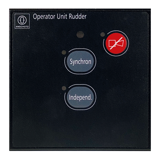
Rudder Mode Operator Unit AS 1 Description 1.5 Operating Elements and Indicators Fig. 4: Rudder Mode Operator Unit AS, Operating Elements and Indicators Pushbutton Independent with green LED Service hole Pushbutton Synchron with green LED Pushbutton ACK with LED Area / Element Description Pushbutton Inde- Activates independent mode... -
Page 18: Operations And Monitoring Elements At The Cpu Pcb
Rudder Mode Operator Unit AS 1 Description Area / Element Description LED (blue) lights up if configuration mode is active 1.6 Operations and Monitoring Elements at the CPU PCB Indications of the (LED)s at the Light Emitting Diode Central Processing Unit (CPU) Printed may be helpful for fault diagnostics. -
Page 19: Functional Description
Rudder Mode Operator Unit AS 1 Description 1.7 Functional Description 1.7.1 Modes of Operation The Rudder Mode Operator Unit AS has following modes of normal operation: Mode Synchronous, see • chapter 1.7.2 chapter 2.3.2 • Mode Independent, see chapter 1.7.2 chapter 2.3.3 1.7.2 ... -
Page 20: Operation
Rudder Mode Operator Unit AS 2 Operation 2 Operation 2.1 Preliminary Remarks User Rights The manual is a complete documentation of the system or equipment. Some functions may not be accessible depending on user rights. All functions or operations are described irrespective of the actual user rights of the user. Markup Elements The manual uses different markup elements for hardware and software. -
Page 21: Normal Operation
Rudder Mode Operator Unit AS 2 Operation 2.3 Normal Operation 2.3.1 Activate Rudder Mode Operator Unit AS Procedure Note After switching on the steering system, the steering control units (tiller / handwheel) are in stand by mode and the Rudder Mode Operator Unit AS is off. 1. -
Page 22: Activate Independent Mode
Rudder Mode Operator Unit AS 2 Operation 2.3.3 Activate Independent Mode Procedure Note The steering control units (handwheel or tiller) must be inactive and should be in center position with no set rudder value. 1. Press pushbutton Independent. ► Independent mode is active. ►... -
Page 23: Troubleshooting
Rudder Mode Operator Unit AS 3 Troubleshooting 3 Troubleshooting 3.1 Alarm Management An alarm is indicated by an acoustical signal and a flashing LED (red) at the pushbutton ACK. By pressing the pushbutton ACK the acoustical signal is muted and the LED lights up constantly (red). -
Page 24: Installation And Maintenance
Rudder Mode Operator Unit AS 4 Installation and Maintenance 4 Installation and Maintenance 4.1 Safety Instructions for Installation and Maintenance WARNING! Danger due to maintenance and service by unskilled personnel Risk of serious injury and material damage • Keep all unskilled personnel away from the working area. •... -
Page 25: Special Tools, Measurement And Test Equipment
Rudder Mode Operator Unit AS 4 Installation and Maintenance Note All spare parts that are produced by Anschütz GmbH are identified in the ISPC by a seven-digit part number. This part number is included in the serial number on the type plate of the equipment. -
Page 26: Configuration Hints
Rudder Mode Operator Unit AS 4 Installation and Maintenance Tab. 6: Terminals at Plug B1 Terminal Remarks Supply voltage +18 V DC to 32 V DC Supply voltage 0 V DC CAN bus termination CAN bus low CAN bus CAN bus GND 4.3.1 ... - Page 27 Rudder Mode Operator Unit AS 4 Installation and Maintenance A repair of the Rudder Mode Operator Unit AS is performed as a replacement of the complete device. After replacement the Rudder Mode Operator Unit AS must be checked for correct functioning. Edition: 001 10000001981...
-
Page 28: Transport And Storage
Rudder Mode Operator Unit AS 5 Transport and Storage 5 Transport and Storage 5.1 Preservation, Packing and Storage Preservation All components / devices require no special preservation procedures. Packing All components / devices are packed with a special protection against humidity. The package contains desiccants and a humidity indicator. -
Page 29: Transport
Rudder Mode Operator Unit AS 5 Transport and Storage Color Indication Inside Humidity Necessary Action 40 % patch: pink > 40 % Desiccants must be replaced Components / devices must be checked for hu- midity, 50 % patch: pink > 50 % Desiccants must be replaced, Packaging must be checked for damages Note... -
Page 30: Disposal
Rudder Mode Operator Unit AS 6 Disposal 6 Disposal The Rudder Mode Operator Unit AS or components of it can be disposed according to the respective national regulations for electronic waste without harmful material. The Rudder Mode Operator Unit AS is designed under . 10000001981 Edition: 001... -
Page 31: Illustrated Spare Parts Catalog
Shows more information about the spare part 7.3 Rudder Mode Operator Unit AS Fig. No. Designation 1. Part No. Remarks Item No. 2. Part No. Rudder Mode Operator Unit AS 4004546 105-311.NG001 Rudder Mode Operator Unit AS 4006598 105-311.NG001 E01 Edition: 001 10000001981... -
Page 32: Annex
Rudder Mode Operator Unit AS 8 Annex 8 Annex 8.1 Applications within a Steering System 8.1.1 Override Function See also The override function can be used in an autopilot mode only. Override is used to interrupt an automatic mode because of a heading change to avoid a collision with another vessel or because of a last moment maneuver. -
Page 33: Deactivate Override Function
Rudder Mode Operator Unit AS 8 Annex Note Independent whether the alarm is acknowledged or not, the respective tiller or handwheel is active. 8.1.1.2 Deactivate Override Function Procedure 1. Make a choice out of the following options to deactivate the override function: a) Press the pushbutton Autopilot at the Override Signal Unit AS. -
Page 34: Synchronous - Independent
Rudder Mode Operator Unit AS 8 Annex Activation of the Give Over Function: • Select and activate the respective steering control unit or units at the Steering Mode Operator Unit AS Deactivation of the Give Over Function: Make a choice out of the following options to deactive the give over function: •...
Need help?
Do you have a question about the 105-311.NG001 and is the answer not in the manual?
Questions and answers