
Related Manuals for Anschutz 138-128.NG001


Summary of Contents for Anschutz 138-128.NG001
- Page 1 Anschütz GmbH Zeyestr. 16-24 24106 Kiel Germany www.anschuetz.com CAN Bus Distribution Unit AS Operator and Service Manual Type: 138-128.NG001 Edition: 001 10000001266...
- Page 2 Copyright Dieses Dokument sowie dessen Inhalt sind urheberrechtlich This document and its content are copyright protected. Distribution, geschützt. Die Weitergabe,Vervielfältigung und Speicherung sowie reproduction and storage as well as translation and exploitation of die Übersetzung wie auch Verwendung dieses Dokuments oder this document and its content, in whole or in parts and regardless of dessen Inhalts, als Ganzes oder in Teilen und egal in welcher Form what form, are prohibited without prior express written permission.
-
Page 3: Table Of Contents
CAN Bus Distribution Unit AS Table of Contents Table of Contents List of Figures..............................III List of Tables................................ V List of Abbreviations............................VII Introduction................................ 1 Change History.............................. 1 Safety................................1 General Safety Regulations........................1 General Safety Instructions........................2 Electrostatic Discharge..........................2 List of Further Documents..........................3 List of Annex Documents.......................... - Page 4 CAN Bus Distribution Unit AS Table of Contents 3.3.1.4.1 Connection of Supply Voltage at Plug B1..............20 3.3.1.4.2 Connection of Single CAN Bus User at Plugs B2, B3, B4, B5........22 3.3.1.4.3 Connection / Termination of Dual CAN Bus at Plugs B7, B8........23 3.3.1.4.4 Connection of Alarm Output at Plug B9..............
-
Page 5: List Of Figures
CAN Bus Distribution Unit AS List of Figures List of Figures Fig. 1: Electrostatic Discharge, Protected Area..................... 2 Fig. 2: Principle of Steering System Application (Example)...................4 Fig. 3: Dual Follow-Up Application for Double Rudder..................5 Fig. 4: Radiating Distribution of Steering Transmitters..................6 Fig. - Page 6 CAN Bus Distribution Unit AS List of Figures 10000001266 Edition: 001...
-
Page 7: List Of Tables
CAN Bus Distribution Unit AS List of Tables List of Tables Tab. 1: Change History............................1 Tab. 2: List of Further Documents......................... 3 Tab. 3: Dimensional Drawings..........................3 Tab. 4: Connection Diagrams..........................3 Tab. 5: CAN Bus, Cable Requirements....................... 10 Edition: 001 10000001266... - Page 8 CAN Bus Distribution Unit AS List of Tables 10000001266 Edition: 001...
-
Page 9: List Of Abbreviations
CAN Bus Distribution Unit AS List of Abbreviations List of Abbreviations Advanced Steering Controller Area Network Central Processing Unit Dual Inline Package Electromagnetic Compatibility ESD Protected Area Electrostatic Discharge Ground International Electrotechnical Commission ISPC Illustrated Spare Parts Catalog Local Area Network Light Emitting Diode NMEA National Marine Electronics Association... - Page 10 CAN Bus Distribution Unit AS List of Abbreviations 10000001266 VIII Edition: 001...
-
Page 11: Introduction
CAN Bus Distribution Unit AS Introduction Introduction Change History Tab. 1: Change History Change Remarks Replaces document 3957 Edition: 001 Safety General Safety Regulations The following safety symbols are used in this manual: WARNING! Warning statements indicate a hazardous situation that, if not avoided, could result in minor, moderate or serious injury, or death Consequence •... -
Page 12: General Safety Instructions
CAN Bus Distribution Unit AS Introduction General Safety Instructions Electrostatic Discharge Fig. 1: Electrostatic Discharge, Protected Area Table Mat Ground Cord Dissipative Shoes Floor Mat Wrist Band Wrist Strap Common Ground Ground Point Any product which is labeled as shown is electrostatic sensitive. If proper precautions are not taken, handling or working on Electrostatic Discharge (ESD) -
Page 13: List Of Further Documents
CAN Bus Distribution Unit AS Introduction List of Further Documents Tab. 2: List of Further Documents Documentation No. Designation 3963 Service Tool AS NB42-232 List of Annex Documents Tab. 3: Dimensional Drawings Documentation No. Designation 138-128.HP005 CAN Bus Distribution AS Tab. -
Page 14: Description
CAN Bus Distribution Unit AS 1 Description 1 Description 1.1 Purpose A CAN Bus Distribution Unit AS is a central component in a ship‘s steering control system. It is designed to distribute information of a dual CAN bus system to connected up to 4 single CAN bus lines. -
Page 15: Dual Follow-Up Application (Example)
CAN Bus Distribution Unit AS 1 Description 1.2.1 Dual Follow-Up Application (Example) Fig. 3: Dual Follow-Up Application for Double Rudder The steering point for a double rudder with a follow-up application consists of 2 tillers which are assigned to rudder 1 and rudder 2. The tiller can be applied in 2 channels, each channel is led via a single line CAN bus to the CAN Bus Distribution Unit AS. -
Page 16: Radiating Distribution Of Steering Transmitters (Example)
CAN Bus Distribution Unit AS 1 Description 1.2.2 Radiating Distribution of Steering Transmitters (Example) Fig. 4: Radiating Distribution of Steering Transmitters Several CAN Bus Distribution Units can be combined and the steering transmitters can be connected radiating from that point. If 1 connected user is disturbed, it affects its function only. Other users or the system CAN bus (dual CAN bus) are not affected (reactionless). -
Page 17: Interfaces
CAN Bus Distribution Unit AS 1 Description 1.4.1 Interfaces Inputs 1x RS232 Development only 1x Dual CAN bus System bus Outputs 4x Single CAN bus +24 V DC 1x Alarm Out System failure Edition: 001 10000001266... -
Page 18: Technical Description
CAN Bus Distribution Unit AS 1 Description 1.5 Technical Description Fig. 5: CAN Bus Distribution Unit AS Block Diagram The data flow, its direction as well as the data itself must be configured before via a special Service Tool. Note Only Anschütz service personnel is permitted to use the Service Tool. 10000001266 Edition: 001... -
Page 19: Can Bus Technology
CAN Bus Distribution Unit AS 1 Description 1.6 CAN Bus Technology bus is a multi-master bus allowing the connection of all Controller Area Network (CAN) devices and systems regardless of their tasks and functions. This means that any number of devices can be connected. These devices must be designed for CAN bus technology. For the CAN bus it is essential that every CAN bus participant is addressable via a unique address. -
Page 20: Operating And Monitoring Elements Of Lower Pcb
CAN Bus Distribution Unit AS 1 Description Tab. 5: CAN Bus, Cable Requirements Term Designation 2 x 2 x 0.75 mm , screened, twisted pair (twisted pitch length Type < 80 mm) Impedance 120 Ω ± 10 % Capacitance max. 50 pF/m Cable line delay max. -
Page 21: Operating And Monitoring Elements Of Upper Pcb
CAN Bus Distribution Unit AS 1 Description Pos. Designation Remarks Pushbutton Resets CPU (after flashing new software) DIP switch Development only 1.8 Operating and Monitoring Elements of Upper PCB Figure and table show all operating and monitoring elements (in the broadest sense) of the upper PCB of the CAN Bus Distribution Unit AS. -
Page 22: Functional Description
CAN Bus Distribution Unit AS 1 Description Pos. Designation Remarks Plug B4 Connects a single CAN bus user LED H9 Flashes (green) during data transfer LED H8 Flashes (green) during data transfer Plug B7 Connects CAN2 of dual CAN bus Fuse E1 24 V DC, 2 A, slow, to protect the CAN Bus Distribution Unit AS it- self and the connected and supplied user Plug B1... -
Page 23: Outfit And Accessories
CAN Bus Distribution Unit AS 1 Description • Take Over Operator Unit AS • Rudder Mode Operator Unit AS • Steering Mode Operator Unit AS • Steering Mode Selector Switch AS • CAN Bus Distribution Unit AS • CAN Bus Gateway AS •... -
Page 24: Operation
CAN Bus Distribution Unit AS 2 Operation 2 Operation After installation and configuration the CAN Bus Distribution Unit AS operates without an operator's influence. 2.1 Setting into Operation Procedure 1. Connect the supply voltage. ► The CAN Bus Distribution Unit AS is in standby and ready for operation. Note There is no separate ON/OFF switch. -
Page 25: Installation And Maintenance
CAN Bus Distribution Unit AS 3 Installation and Maintenance 3 Installation and Maintenance 3.1 Safety Instructions for Installation and Maintenance WARNING! Danger due to maintenance and service by unskilled personnel Risk of serious injury and material damage • Keep all unskilled personnel away from the working area. •... -
Page 26: Special Tools, Measurement And Test Equipment
CAN Bus Distribution Unit AS 3 Installation and Maintenance Note All spare parts that are produced by Anschütz GmbH are identified in the ISPC by a seven-digit part number. This part number is included in the serial number on the type plate of the equipment. -
Page 27: General Remarks About Preparing Cable Connections
CAN Bus Distribution Unit AS 3 Installation and Maintenance WARNING! Danger due to damaged cable coating Risk of fire or electrical shock • Do not bend cables to an acute angle, pinch, twist, or impact excessive force while connecting cables to the equipment. •... -
Page 28: Fig. 10: Prepare A Cable Entry
CAN Bus Distribution Unit AS 3 Installation and Maintenance Fig. 10: Prepare a Cable Entry 7. Insert the earthing insert, the seal, and the washer into the cable gland, place the counter nut last and tighten the nut hand-tight. 8. Strip the cable cores to a length of approx. 15 mm, twist slightly and clamp on the cable end sleeves. -
Page 29: General Remarks About Preparing Common Ground Connections
CAN Bus Distribution Unit AS 3 Installation and Maintenance 3.3.1.3 General Remarks about Preparing Common Ground Connections In order to comply with the stringent requirements, Electromagnetic Compatibility (EMC) please follow the instructions given below regarding cable connections. Use the cable types specified. CAUTION! Damage to Equipment and Components It is essential to make sure that any equipment and any additional... -
Page 30: Connection Of Supply Voltage At Plug B1
CAN Bus Distribution Unit AS 3 Installation and Maintenance Fig. 13: CAN Bus Distribution Unit AS Connections (Recommendations) Connection Plug Reference chapter 3.3.1.4.1 Supply voltage chapter 3.3.1.4.2 Single CAN bus output B2, B3, B4, B5 chapter 3.3.1.4.3 Dual CAN bus B7, B8 chapter 3.3.1.4.4 Alarm output 3.3.1.4.1 ... -
Page 31: Fig. 14: Supply Voltage At Plug B1
CAN Bus Distribution Unit AS 3 Installation and Maintenance Fig. 14: Supply Voltage at Plug B1 Plug / Terminal Scheme Remarks B1/1 +24 V DC B1/2 +24 V DC B1/3 B1/4 Edition: 001 10000001266... -
Page 32: Connection Of Single Can Bus User At Plugs B2, B3, B4, B5
CAN Bus Distribution Unit AS 3 Installation and Maintenance 3.3.1.4.2 Connection of Single CAN Bus User at Plugs B2, B3, B4, B5 Fig. 15: Single CAN Bus at Plugs B2, B3, B4, B5 Plug / Terminal Remarks B2/1, B3/1, B4/1, B5/1 24 V DC supply for connected user B2/2, B3/2, B4/2, B5/2 0 V supply for connected user... -
Page 33: Connection / Termination Of Dual Can Bus At Plugs B7, B8
CAN Bus Distribution Unit AS 3 Installation and Maintenance 3.3.1.4.3 Connection / Termination of Dual CAN Bus at Plugs B7, B8 Fig. 16: Dual CAN Bus at Plugs B7, B8 Plug / Terminal Remarks B7/1, B8/1 CAN termination (jumper between terminal 1 and 2) B7/2, B8/1 CAN low B7/3, B8/3... -
Page 34: Connection Of Alarm Output At Plug B9
CAN Bus Distribution Unit AS 3 Installation and Maintenance Fig. 17: Principle of a Dual CAN Bus Application Termination (terminal 1) CAN low (terminal 2) CAN high (terminal 3) CAN ground (terminal 4) 3.3.1.4.4 Connection of Alarm Output at Plug B9 Fig. -
Page 35: Configuration
CAN Bus Distribution Unit AS 3 Installation and Maintenance Plug / Terminal Remarks B9/1 B9/2 B9/3 Note Alarm outputs must be connected to a central alarm panel / signal unit. Alarm panel or signal unit must have an acoustical and optical alarm indication. 3.3.2 ... - Page 36 CAN Bus Distribution Unit AS 3 Installation and Maintenance After replacement, the CAN Bus Distribution Unit AS must be checked for correct functioning. 10000001266 Edition: 001...
-
Page 37: Transport And Storage
CAN Bus Distribution Unit AS 4 Transport and Storage 4 Transport and Storage 4.1 Preservation, Packing and Storage Preservation All components / devices require no special preservation procedures. Packing All components / devices are packed with a special protection against humidity. The package contains desiccants and a humidity indicator. -
Page 38: Transport
CAN Bus Distribution Unit AS 4 Transport and Storage Color Indication Inside Humidity Necessary Action 40 % patch: pink > 40 % Desiccants must be replaced Components / devices must be checked for hu- midity, 50 % patch: pink > 50 % Desiccants must be replaced, Packaging must be checked for damages Note... -
Page 39: Disposal
CAN Bus Distribution Unit AS 5 Disposal 5 Disposal The CAN Bus Distribution Unit AS or components of it can be disposed according to the respective national regulations for electronic waste without harmful materials (according to Directive 2012/19/EU on waste electrical and electronic equipment (WEEE)). Edition: 001 10000001266... -
Page 40: Spare Parts Catalog
CAN Bus Distribution Unit AS 6 Spare Parts Catalog 6 Spare Parts Catalog 6.1 General Remarks All depicted items in the following figure(s) which are not mentioned in the corresponding table(s) are not available as spare part for this unit. Since further development may cause modifications to existing equipment, its conformity with the relevant illustrations and drawings is not always ensured. -
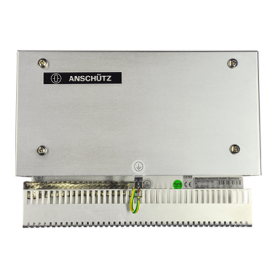
Page 41: Can Bus Distribution Unit As
CAN Bus Distribution Unit AS 6 Spare Parts Catalog 6.3 CAN Bus Distribution Unit AS Fig. 19: 00-0000 Fig. No. Designation 1. Part No. Remarks Item No. 2. Part No. 00-0000 CAN Bus Distribution Unit AS 4002796 138-128.NG001 Edition: 001 10000001266... -
Page 42: Annex
CAN Bus Distribution Unit AS 7 Annex 7 Annex 7.1 Drawings 10000001266 Edition: 001...
Need help?
Do you have a question about the 138-128.NG001 and is the answer not in the manual?
Questions and answers