
Related Manuals for Anschutz 135-111.NG003


Summary of Contents for Anschutz 135-111.NG003
- Page 1 Anschütz GmbH Zeyestr. 16-24 24106 Kiel Germany www.anschuetz.com Alarm Signal Unit AS Operator and Service Manual Type: 135-111.NG003 Edition: 001 10000001980...
- Page 2 Copyright Dieses Dokument sowie dessen Inhalt sind urheberrechtlich This document and its content are copyright protected. Distribution, geschützt. Die Weitergabe,Vervielfältigung und Speicherung sowie reproduction and storage as well as translation and exploitation of die Übersetzung wie auch Verwendung dieses Dokuments oder this document and its content, in whole or in parts and regardless of dessen Inhalts, als Ganzes oder in Teilen und egal in welcher Form what form, are prohibited without prior express written permission.
-
Page 3: Table Of Contents
Alarm Signal Unit AS Table of Contents Table of Contents List of Figures..............................III List of Tables................................ V List of Abbreviations............................VII Introduction................................ 1 Preliminary Remarks............................. 1 Change History.............................. 1 Safety................................1 General Safety Regulations........................1 General Safety Instructions........................2 Electrostatic Discharge..........................2 List of Further Documents..........................3 List of Annex Documents.......................... - Page 4 Alarm Signal Unit AS Table of Contents 4.1 Safety Instructions for Installation and Maintenance................21 4.2 General Information..........................21 4.2.1 Reference to ISPC.........................21 4.2.2 Special Tools, Measurement and Test Equipment............... 22 4.2.3 List of Consumables........................22 4.3 Installation............................... 22 4.3.1 Cable Connections.........................22 4.3.1.1 Safety Instructions for Cable Connections................22 4.3.1.2 General Remarks about Preparing Cable Connections............
-
Page 5: List Of Figures
Alarm Signal Unit AS List of Figures List of Figures Fig. 1: Electrostatic Discharge, Protected Area..................... 2 Fig. 2: CAN Bus, Jumper for Termination......................6 Fig. 3: Alarm Signal Unit AS, Operating Elements and Indicators.................8 Fig. 4: Alarm Signal Unit AS, Status Fields......................9 Fig. - Page 6 Alarm Signal Unit AS List of Figures 10000001980 Edition: 001...
-
Page 7: List Of Tables
Alarm Signal Unit AS List of Tables List of Tables Tab. 1: Change History............................1 Tab. 2: List of Further Documents......................... 3 Tab. 3: Dimensional Drawings..........................3 Tab. 4: Wiring Diagrams............................3 Tab. 5: Configuration Sheet............................3 Tab. 6: CAN Bus, Cable Requirements......................... 7 Tab. - Page 8 Alarm Signal Unit AS List of Tables 10000001980 Edition: 001...
-
Page 9: List Of Abbreviations
Alarm Signal Unit AS List of Abbreviations List of Abbreviations Controller Area Network Central Processing Unit ESD Protected Area Electrostatic Discharge Follow-Up Ground ISPC Illustrated Spare Parts Catalog Non-Follow-Up Edition: 001 10000001980... - Page 10 Alarm Signal Unit AS List of Abbreviations 10000001980 VIII Edition: 001...
-
Page 11: Introduction
Alarm Signal Unit AS Introduction Introduction Preliminary Remarks The present manual is a description and reference book only. It is intended to answer questions and to solve problems in the quickest possible manner. Read and follow the instructions and notes in this manual before operating the equipment. For this purpose, refer to the table of contents and read the corresponding chapters thoroughly. -
Page 12: General Safety Instructions
Alarm Signal Unit AS Introduction WARNING! Warning statements indicate a hazardous situation that, if not avoided, could result in minor, moderate or serious injury, or death Consequence • Preventive action CAUTION! Caution statements indicate a hazardous situation that, if not avoided, could result in material damage Consequence •... -
Page 13: List Of Further Documents
Alarm Signal Unit AS Introduction Dissipative Shoes Floor Mat Wrist Band Wrist Strap Common Ground Ground Point Any product which is labeled as shown is electrostatic sensitive. If proper Electrostatic Discharge (ESD) precautions are not taken, handling or working on this product results in damage. -
Page 14: Description
Alarm Signal Unit AS 1 Description 1 Description 1.1 Purpose The Alarm Signal Unit AS is designed to indicate / display alarms, warnings and messages. 1.2 Technical Data Height 94 mm Dimensions Width 192 mm Depth 89 mm Weight Approx. 1 kg Protection Class IP 23 / IP 56 Voltage Supply... -
Page 15: Technical Description
Alarm Signal Unit AS 1 Description Designation Description Plug Information (via relays) from external devices. Infor- mation is converted to CAN bus format and can influ- ence the control of the steering elements (depends on Digital input configuration). The information is not converted to switching outputs or to a serial output. -
Page 16: Can Bus Technology
Alarm Signal Unit AS 1 Description The Alarm Signal Unit AS has a built-in signal horn. This horn gives an acoustical sound when an alarm occurs. 1.3.1 CAN Bus Technology Controller Area Network (CAN) bus is a multi-master bus allowing the connection of all devices and systems regardless of their tasks and functions. -
Page 17: Nautosteer As
Alarm Signal Unit AS 1 Description The minimum cable requirements for the CAN bus are: Tab. 6: CAN Bus, Cable Requirements Term Designation 2 x 2 x 0.75 mm , screened, twisted pair (twisted pitch length Type < 80 mm) Impedance 120 Ω... -
Page 18: Operating Elements And Indicators
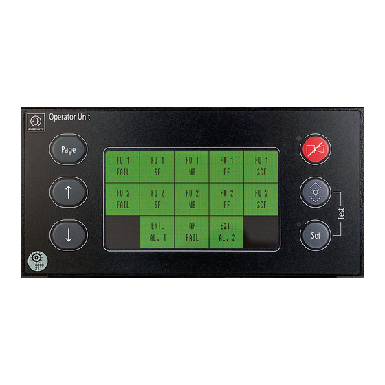
Alarm Signal Unit AS 1 Description 1.4 Operating Elements and Indicators Fig. 3: Alarm Signal Unit AS, Operating Elements and Indicators Tab. 7: Alarm Signal Unit AS, Indicators Description Designation / Function Pushbutton Page Shows a table with occurred alarms and warnings Pushbutton ↑... -
Page 19: Display Organization
Alarm Signal Unit AS 1 Description 1.5 Display Organization 1.5.1 Main Page with Status Fields Up to 15 status fields are configurable. The text string and the color of each status field can be configured. This configuration depends on the application of the Alarm Signal Unit AS and the alarms, warnings or messages which should be evaluated and indicated. -
Page 20: Functional Description
Alarm Signal Unit AS 1 Description Time and date of acknowledgement and date or time when cleared are shown at the bottom of the display. Fig. 5: Alarm Signal Unit AS, Alarms and Warnings Display Alarm and warnings are displayed in their sequence of occurrence. A maximum of 25 alarms or warnings can be displayed. -
Page 21: Operation
Alarm Signal Unit AS 2 Operation 2 Operation 2.1 Preliminary Remarks User Rights The manual is a complete documentation of the system or equipment. Some functions may not be accessible depending on user rights. All functions or operations are described irrespective of the actual user rights of the user. Markup Elements The manual uses different markup elements for hardware and software. -
Page 22: Setting Into Operation
Alarm Signal Unit AS 2 Operation 2.3 Setting into Operation 2.3.1 Pre-Operation Procedures after Longer Time Setting out of Operation This system or equipment requires no special pre-operation procedures after longer time setting out of operation. 2.4 Normal Operation Procedures 2.4.1 Select Display Page Procedure 1. -
Page 23: Emergency Operation Procedures
Alarm Signal Unit AS 2 Operation Note If there is no date and time (UTC) available, the time displayed is the operating hours. 2.5 Emergency Operation Procedures This system or equipment has no emergency operation function. 2.6 Setting out of Operation 2.6.1 ... -
Page 24: Troubleshooting
Alarm Signal Unit AS 3 Troubleshooting 3 Troubleshooting 3.1 Alarm Handling Alarms and warnings are displayed at the Alarm Signal Unit AS. Additionally, an acoustical signal sound. If an alarm occurs, • the respective status field flashes red • the message bar flashes red and indicates a text message •... -
Page 25: Monitoring Elements At Cpu Pcb And Connection Pcb
Alarm Signal Unit AS 3 Troubleshooting Status field Type of Infor- Source Text message Possible cause mation Autopilot Alarm (red) Relay at the Au- AUTOPILOT System failure topilot - SYSTEM FAILURE Autopilot Alarm (red) CAN AP AUTOPILOT - Off heading OFF HEADING Autopilot Alarm (red) CAN AP... -
Page 26: Fig. 6: Cpu Pcb, Monitoring Elements
Alarm Signal Unit AS 3 Troubleshooting CPU PCB Fig. 6: CPU PCB, Monitoring Elements Designation Function DIP Switch B11 Development only Pushbutton Reset to reset the microcontroller Pushbutton B7 Pushbutton B10 Pushbutton Set with illumination LEDs (white) LED H11 LED H14 Pushbutton Dim with illumination LEDs (white) Pushbutton B9 LED H9... - Page 27 Alarm Signal Unit AS 3 Troubleshooting Designation Function Pushbutton B8 Pushbutton ACK with illumination LEDs (white) LED H8 LED H12 LED H7 LED ALARM (red or green) Red flashing: an alarm or a warning is active and must be ac- knowledged Red: an already acknowledged alarm or warning is still present Green: currently not used Pushbutton B2...
-
Page 28: Fig. 7: Connection Pcb, Monitoring Elements
Alarm Signal Unit AS 3 Troubleshooting Connection PCB Fig. 7: Connection PCB, Monitoring Elements Designation Function Plug B4 Relay output System Fail Can operate as active open or active closed Active closed is a Alarm Signal Unit AS failure Plug B9 24 V DC supply voltage input LED H1 Lights up (red) if System Fail is active closed... - Page 29 Alarm Signal Unit AS 3 Troubleshooting Designation Function Switch B2 Is used to terminate Serial In at plug B5 LED H4 Lights up (green) if Relay Switching Output 1 is active LED H10 Lights up (green) if Relay Switching Output 3 is active Plug B6 Relay Switching Output 1 and Relay Switching Output 2 Plug B11...
-
Page 30: Perform Test
Alarm Signal Unit AS 3 Troubleshooting Designation Function Plug B10 Digital Input1 and Digital Input2 LED H8 Lights up (green) if a digital input bridges the terminals 1 and 2 of plug B10 LED H13 Flashes (green) ALIVE if the Alarm Signal Unit AS is in normal operation Horn H12 Signal horn for acoustical signal... -
Page 31: Installation And Maintenance
Alarm Signal Unit AS 4 Installation and Maintenance 4 Installation and Maintenance 4.1 Safety Instructions for Installation and Maintenance WARNING! Danger due to maintenance and service by unskilled personnel Risk of serious injury and material damage • Keep all unskilled personnel away from the working area. •... -
Page 32: Special Tools, Measurement And Test Equipment
Alarm Signal Unit AS 4 Installation and Maintenance Note All spare parts that are produced by Anschütz GmbH are identified in the ISPC by a seven-digit part number. This part number is included in the serial number on the type plate of the equipment. The first 7 digits of the serial number are formed by the part number. -
Page 33: General Remarks About Preparing Cable Connections
Alarm Signal Unit AS 4 Installation and Maintenance 4.3.1.2 General Remarks about Preparing Cable Connections WARNING! Danger due to electrical current Risk of death or serious injury or material damage • Make sure that all cables are disconnected from the power supply. •... -
Page 34: Fig. 9: Prepare A Cable Entry
Alarm Signal Unit AS 4 Installation and Maintenance Fig. 9: Prepare a Cable Entry 7. Insert the earthing insert, the seal, and the washer into the cable gland, place the counter nut last and tighten the nut hand-tight. 8. Strip the cable cores to a length of approx. 15 mm, twist slightly and clamp on the cable end sleeves. -
Page 35: General Remarks About Preparing Common Ground Connections
Alarm Signal Unit AS 4 Installation and Maintenance 4.3.1.3 General Remarks about Preparing Common Ground Connections In order to comply with the stringent requirements, please follow the instructions given below regarding cable connections. Use the cable types specified. CAUTION! Damage to Equipment and Components It is essential to make sure that any equipment and any additional component (options) have common reference to the ship's common ground. -
Page 36: Fig. 12: Supply Voltage Connection At Plug B9
Alarm Signal Unit AS 4 Installation and Maintenance Note By connecting the supply (24 V DC), the Alarm Signal Unit AS is set into operation. There is no separate power switch. Fig. 12: Supply Voltage Connection at Plug B9 Plug / Terminal Scheme Remarks B9/1... -
Page 37: Can Bus At Plugs B7, B8
Alarm Signal Unit AS 4 Installation and Maintenance 4.3.1.4.2 CAN Bus at Plugs B7, B8 Fig. 13: CAN Bus Connection at Plugs B7, B8 Plug / Terminal Remarks B7/1, B8/1 CAN termination (jumper between terminal 1 and 2) B7/2, B8/2 CAN low B7/3, B8/3 CAN high B7/4, B8/4... -
Page 38: Status Output Sys Fail At Plug B4
Alarm Signal Unit AS 4 Installation and Maintenance 4.3.1.4.3 Status Output SYS FAIL at Plug B4 Fig. 14: Status Output System Failure at Plug B4 Plug / Terminal Scheme B4/1 B4/3 B4/2 4.3.1.4.4 Serial In and Serial Out at Plug B5 Fig. -
Page 39: Relay Switching Outputs 1 To 4 At Plugs B6, B11
Alarm Signal Unit AS 4 Installation and Maintenance Plug / Terminal Remarks RS422 RS485 B5/1 B5/2 B5/3 N.C. B5/4 N.C. B5/5 Note Observe termination switches B1 (RS422 Out) and B2 (RS422 In). Observe switch position of B14, B17 and B16 for RS485 operation. chapter 3.2. -
Page 40: Digital Inputs 1 To 2 At Plug B10
Alarm Signal Unit AS 4 Installation and Maintenance Plug / Terminal Scheme Remarks B6/4, B11/4 B6 = Output 2 B11 = Output 4 B6/6, B11/6 B6/5, B11/5 4.3.1.4.6 Digital Inputs 1 to 2 at Plug B10 Fig. 17: Digital Inputs at Plug B10 Plug / Terminal Remarks Digital In... -
Page 41: Care And Maintenance
Alarm Signal Unit AS 4 Installation and Maintenance = Alarm Amber = Status message, warning Green = Proper function Gray = Off Light gray = Not used • Text strings for each status field • Text message(s) for alarms and warnings for each status field •... -
Page 42: Care And Maintenance
Alarm Signal Unit AS 4 Installation and Maintenance 4.6 Care and Maintenance The Alarm Signal Unit AS does not require special care and is maintenance-free. 4.7 Repair CAUTION! Hazard due to wear and tear of electromechanical devices such as relays, switches or potentiometers Risk of malfunction •... -
Page 43: Transport And Storage
Alarm Signal Unit AS 5 Transport and Storage 5 Transport and Storage 5.1 Preservation, Packing and Storage Preservation All components / devices require no special preservation procedures. Packing All components / devices are packed with a special protection against humidity. The package contains desiccants and a humidity indicator. -
Page 44: Transport
Alarm Signal Unit AS 5 Transport and Storage Color Indication Inside Humidity Necessary Action 40 % patch: pink > 40 % Desiccants must be replaced Components / devices must be checked for hu- midity, 50 % patch: pink > 50 % Desiccants must be replaced, Packaging must be checked for damages Note... -
Page 45: Disposal
Alarm Signal Unit AS 6 Disposal 6 Disposal The Alarm Signal Unit AS or components of it can be disposed according to the respective national regulations for electronic waste without harmful materials (according to Directive 2012/19/EU on waste electrical and electronic equipment (WEEE)). Edition: 001 10000001980... -
Page 46: Illustrated Spare Parts Catalog
(Quantity Installed) Remarks Shows more information about the spare part 7.3 Alarm Signal Unit AS Fig. No. Designation 1. Part No. Remarks Item No. 2. Part No. Alarm Signal Unit AS 135-111.NG003 E01 4006360 10000001980 Edition: 001... -
Page 47: Annex
Alarm Signal Unit AS 8 Annex 8 Annex 8.1 Drawings Edition: 001 10000001980... - Page 48 Alarm Signal Unit AS 8 Annex 10000001980 Edition: 001...
Need help?
Do you have a question about the 135-111.NG003 and is the answer not in the manual?
Questions and answers