
Related Manuals for ABB TruFit PDU 750 kVa


Summary of Contents for ABB TruFit PDU 750 kVa
- Page 1 — 94-1100-00002878 B INSTALLATION GUIDE TruFit™ Power Distribution Unit 750/850/950 kVA...
- Page 2 PDU. Thank you for choosing ABB! Start-up and commissioning! An ABB Global Services Field Engineer must perform start-up and commissioning of the PDU. Please contact ABB Service Center at least two weeks prior to schedule start-up and commissioning at 1-800-292-3739.
- Page 3 We are an established world force in the design and manufacture of power electronics and power protection equipment. As a part of ABB, a world leader in electrical technology, we offer customers application expertise, service, and support worldwide. We are committed to teamwork, high quality manufacturing, advanced technology and unrivalled service and support.
-
Page 4: Table Of Contents
Installation Guide Table of contents Page 1 Important safety instructions ............................. 5 Using this manual .................................... 5 1.1.1 List of symbols ....................................5 Safety rules ....................................... 6 Safety precautions ..................................7 Safety considerations ..................................7 2 Environment ................................... 8 Recycling instructions ..................................8 3 Layout ..................................... -
Page 5: Important Safety Instructions
Perform only those procedures that apply to the PDU cabinet being installed or operated. This unit is equipped with ABB’s PowerView monitoring system. Instructions regarding monitoring can be found in manual 94-1100-00002861. The reader is expected to know the fundamentals of electricity, wiring, electrical components, and electrical schematic symbols. -
Page 6: Safety Rules
This may require additional field marking or labelling defining appropriate level of PPE (Personal Protection Equipment) to reduce the risk of Arc-flash related injuries. Contact our ABB Service Center for product specific information. Installation This PDU must be installed and connected only by trained personnel. -
Page 7: Safety Precautions
As lethal voltages are present within the PDU during all modes of operation, maintenance shall only be performed by authorized service personnel. ABB neither recommends nor knowingly sells this product for use with life support applications or other FDA designed critical applications. -
Page 8: Environment
PDU packing materials must be recycled in compliance with all applicable regulations. Recycling at the end of service life! ABB, in compliance with environment protection recommends to the User that the PDU equipment must be recovered at the end of its service life, to conform to the local applicable regulations. -
Page 9: Layout
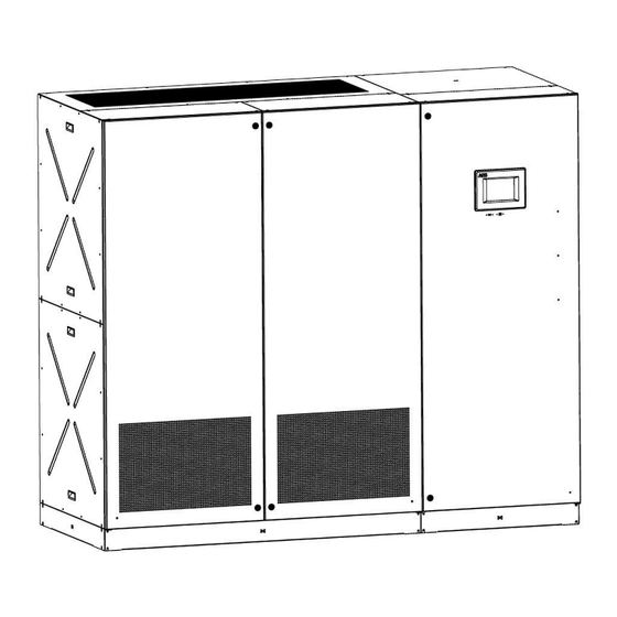
Installation Guide 3 Layout 3.1 Layout TruFit™ PDU 750/850/950 kVA Vented Top Plate Touchscreen Display Front Door Transformer Ventilation Intake Side Panel Kickplates Figure 3.1.1 – Main cabinets with doors closed 750/850/950 kVA TruFit Power Distribution Unit│94-1100-00002878 B EN 9/38... - Page 10 Installation Guide Logic Power SPD Isolation Isolation Switch Switch SMB Maintenance Mode Key Switch SPD Slide Handle MCB01 SPD Surge Counter Solid Transformer Deadfront Perforated Transformer Deadfront Figure 3.1.2 – Transformer cabinet with doors open 10/38 94-1100-00002878 B EN│750/850/950 kVA TruFit Power Distribution Unit...
- Page 11 Installation Guide Subfeed Breakers Hinged Logic Compartment Deadfront Figure 3.1.3 –850/950kVA Distribution cabinet with doors open 750/850/950 kVA TruFit Power Distribution Unit│94-1100-00002878 B EN 11/38...
- Page 12 Installation Guide Tahuya Alternate Control Communication Power Input Converter Terminations PowerView User Interface Monitoring Module Board Figure 3.1.4 – 850/950kVA Distribution cabinet with doors open; Logic Compartment Subfeed Breakers Tahuya Alternate Control Communication Power Input Converter Terminations PowerView User Interface Monitoring Module Board Figure 3.1.5 –...
-
Page 13: Installation
If damage is observed, file a damage claim with the shipper immediately and contact your ABB representative to inform them of the equipment condition and claim. -
Page 14: Dimensions And Weights
Installation Guide 4.2.1 Dimensions and weights Figure 4.2.2 - TruFit™ PDU 850/950 kVA Dimensions Dimensions (W x D x H): TruFit™ PDU 850kVA 84.0 x 36.0 x 78.0 [inches] / 2132 x 914 x 1981 [mm] TruFit™ PDU 950kVA 90.0 x 36.0 x 78.0 [inches] / 2286 x 914 x 1981 [mm] Approximate Weight: TruFit™... - Page 15 Installation Guide Figure 4.2.3 - TruFit™ PDU 750 kVA Dimensions Dimensions (W x D x H): TruFit™ PDU 750kVA 120.0 x 36.0 x 78.0 [inches] / 3048 x 914 x 1981 [mm] Approximate Weight: TruFit™ PDU 750kVA 750kVA cabinet 6340 lbs. 2876 kg 750/850/950 kVA TruFit Power Distribution Unit│94-1100-00002878 B EN 15/38...
-
Page 16: Storage
4.4 Place of installation 4.4.1 PDU location PDU installation and connection must be performed only by an ABB Service Technician! If optional cabinets and accessories are included with the PDU, please refer to those accompanying manuals for installation and operating instructions. -
Page 17: Positioning Of The Pdu
Refer to section 4.2.1 for weight and dimensional specifications of your ABB product. If additional raised floor supports are required, contact your raised flooring supplier or ABB for either floor jacks or full frame floor stand specifications. 4.4.3 Access The system is designed to allow the customer to use every available square foot of computer room space for operating your computers versus your power conditioning equipment. -
Page 18: Checking The Supplied Parts
Your TruFit™ PDU is protected by stretch wrap material to protect the system’s heat treated, matte finished, and powder coated paint against abrasion and vibration during transit. In addition, ABB then protects each of the four corners with double wall corrugated corner boards which protect the unit during transit. -
Page 19: Ventilation And Cooling
PDU. Ensure that the ambient temperature is kept within the specified operating range of 32°F to 104°F (0°C to 40°C). Contact your ABB Service Center for appropriate solutions. The below table indicates the heat dissipation at full resistive load at PF = 1, up to 3280 ft (1000 m) altitude. -
Page 20: Main Cabinet Installation
As lethal voltages exist within all operating modes of the PDU, maintenance must be performed by qualified and trained service personnel. ABB neither recommends nor knowingly sells this product for use with life support applications or other FDA-designated critical applications. ... - Page 21 Once additional cabinet is in place, secure the (5) plates to rails of the subfeed breaker cabinet in which they align with using (2) Phillips pan head thread rolling screws, ABB P/N 09-2200-00001930, per bracket. Refer Figure 4.8.3. Figure 4.8.3 – Additional sidecar cabinet mounting plate & screws If an additional sidecar cabinet is provided refer to Figure 4.8.4 for mounting after the additional sidecar has been...
- Page 22 Installation Guide Figure 4.8.4 – Additional sidecar cabinet mounting features After securing the (5) plates to the rails of the subfeed breaker cabinet fasten the additional cabinet to the floor using the exact same method which was used to fasten the transformer and subfeed breaker cabinet to the floor. Figure 4.8.5 –...
-
Page 23: Kick Plate Installation Instructions
Installation Guide Open door and remove deadfront panel on additional sidecar to gain access to ground bus. Connect provided ground cable assembly to ground bus (3/8” Lug) from distribution cabinet frame using provided hardware kit (PN: 4NWR001341), refer to figure 4.8.6 for details. Torque to specification found in section 5-2. Figure 4.8.6 –... - Page 24 Installation Guide Figure 4.8.6 - Kick plate cosmetic cap installation Figure 4.8.7 - Kick plate positioning at bottom of unit 24/38 94-1100-00002878 B EN│750/850/950 kVA TruFit Power Distribution Unit...
-
Page 25: Electrical Wiring
Installation Guide 4.9 Electrical wiring Upstream overcurrent protective devices (OCPD) must be provided by the customer in accordance with the NEC and local codes. 4.9.1 Pre-checks The TruFit™ PDU is designed for operation with a three (3) wire grounded source. The unit is designed to operate from a power source with a phase rotation of A-B-C only. -
Page 26: Main Input Circuit Installation
Table 4.9.1: Maximum Recommended Cable Sizes and Compression Lugs – Input Terminals Use lugs consistent with applicable codes; ABB recommends the long barrel, NEMA 2-Hole compression lugs shown in Table 4.9.1 for connections to the TruFit™ PDU using code stranded conductors. For all input and output power circuit connections, ABB recommends using SAE Grade 5 hardware with Belleville spring washers. -
Page 27: Control/Auxiliary Circuit Installation
Installation Guide Use lugs consistent with applicable codes; ABB recommends the long barrel, NEMA 2-Hole compression lugs shown in Table 4.9.2 for connections to the TruFit™ PDU using code stranded conductors. For all input and output power circuit connections, ABB recommends using SAE Grade 5 hardware with Belleville spring washers. Always use two (2) wrenches when tightening connections to prevent distortion or damage. - Page 28 Installation Guide Figure 4.9.9 - Suggested control power and communication wire entry Figure 4.9.10 – Control power or communication wire into front Ty-duct Figure 4.9.11 – Control power or communication wire into logic box from front Ty-duct 28/38 94-1100-00002878 B EN│750/850/950 kVA TruFit Power Distribution Unit...
- Page 29 Installation Guide Figure 4.9.12 – Control power or communication wire into rear Ty-duct Figure 4.9.13 – Control power or communication wire into logic box from rear Ty-duct 750/850/950 kVA TruFit Power Distribution Unit│94-1100-00002878 B EN 29/38...
- Page 30 Installation Guide Figure 4.9.14 – 850/950 Alternate control power source terminations 30/38 94-1100-00002878 B EN│750/850/950 kVA TruFit Power Distribution Unit...
- Page 31 Installation Guide Figure 4.9.15 – 750KVA Alternate control power source terminations 750/850/950 kVA TruFit Power Distribution Unit│94-1100-00002878 B EN 31/38...
-
Page 32: Thermocouple Installation
Thermocouple sensors have a standard cable length of 15ft. Terminals or crimped connections should not be used to extend cable lengths, as signal loss will occur, and affect temperature readings. Thermocouple cable installation is typically performed by ABB personnel, but individual situations may dictate otherwise. ... -
Page 33: User Interface Board
Installation Guide 4.10 User Interface Board The User-Interface Board (UIB) provides an interface for connecting the PDU to external monitoring and control equipment. The main features of this board include the following items. (Also see Figure 4.4.1 below.) Alarm relay contacts (Form C) Alarm designation Terminals (J12) Contact type... - Page 34 Installation Guide Slave SHIELD RS-485 (FULL DUPLEX) SHIELD FX BOARD RS-485 (FULL DUPLEX) Master Figure 4.10.1 - UIB connection points. See Section 4.9.5 for control wire routing. 34/38 94-1100-00002878 B EN│750/850/950 kVA TruFit Power Distribution Unit...
-
Page 35: Tahuya Device
Appendix section of this document. Verify all breakers are in the open position. ABB Service Center personnel can provide a more detailed final checklist prior to energizing the unit. 750/850/950 kVA TruFit Power Distribution Unit│94-1100-00002878 B EN 35/38... -
Page 36: Appendix
Installation Guide 5 Appendix 5.1 Notes form It is recommended to note in this section Notes, with date and short description all the operations performed on the PDU, as: maintenance, components replacement, abnormal situations, etc. Date Description Done by 36/38 94-1100-00002878 B EN│750/850/950 kVA TruFit Power Distribution Unit... -
Page 37: Tightening Torques
Installation Guide 5.2 Tightening torques Recommended tightening torque for all nuts and bolts is listed in the table below. As applicable, torque seal has been utilized to indicate bolt torqueing. Table 5-1: Recommended tightening torque SAE Grade 5 Thread 120,000 psi Size Medium Carbon Heat T. - Page 38 We reserve the right to make technical changes Electrification Products or modify the contents of this document without Power Protection prior notice. With regard to purchase orders, the agreed particulars shall prevail. ABB does not 5900 Eastport Boulevard accept responsibility whatsoever...
Need help?
Do you have a question about the TruFit PDU 750 kVa and is the answer not in the manual?
Questions and answers