Table of Contents

Related Manuals for Cincinnati 220-R-2


Summary of Contents for Cincinnati 220-R-2
- Page 1 OPERATION, SAFETY AND MAINTENANCE MANUAL FOR 220-R-2 AND 600-R-3 RIGID RESTRIKE PRESSES C I N C I N N A T I I N C O R P O R A T E D C I N C I N N A T I ,...
-
Page 2: Table Of Contents
RIGID RESTRIKE PRESSES CONTENTS SECTION 1 IDENTIFICATION SECTION 2 INSTALLATION UNLOADING INSPECTION LIFTING AND MOVING FOUNDATION LEVELING CLEANING FINAL CONNECTIONS LUBRICATION SECTION 3 SAFETY SAFETY RECOMMENDATIONS SAFE OPERATION OF YOUR PRESS SAFE OPERATING RULES GUIDELINES FOR INSTALLING, REMOVING AND TRANSFERRING TOOLING SAFETY SIGNS SAFETY GUIDELINES SAFETY MAINTENANCE CHECK... - Page 3 DESCRIPTION PROCEDURE APPLICATION PART UNLOADER PART ORIENTER FLOATING CORE ROD FLOATING CORE ROD STOP (600-R-3 Only) FLOATING DIE (600-R-3 Only) HYDRAULIC FLOATING DIE (220-R-2 Only) OPERATION OF FLOATING DIE CIRCUIT INITIAL CHARGING MAINTENANCE POWER OPERATED TOOL HOIST TONDICATOR CYCLE DELAYS...
- Page 4 RUNNING THE SELF-TEST 9-13 LED INDICATORS ON THE CPU 9-13 CHECKING POWER SUPPLIES 9-14 MAINTENANCE CHECKLIST 9-15 SECTION 10 SERVICE & PARTS ORDERING REPAIR PARTS 10-1 RETURNING PARTS FOR CREDIT 10-1 SERVICE 10-1 TECHNICAL TRAINING 10-1 © COPYRIGHT 2000 CINCINNATI INCORPORATED...
-
Page 5: Rigid Restrike Presses
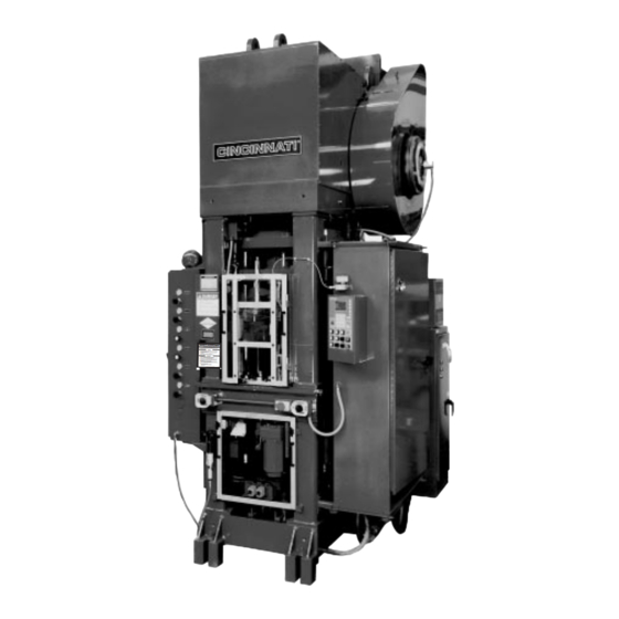
SECTION 1 IDENTIFICATION RIGID RESTRIKE PRESS TOOL HOIST (600-R-3 Only, 8. DIE TABLE 16. GATE OPERATING CYLINDER Not Shown) 9. PART FEED DIAL DRIVE 17. D.C. DRIVE TRANSFORMER MAIN SHAFT ENCODER 10. LOWER FRONT GUARD 18. OPERATOR CONTROLS (Inside cover) 11. - Page 6 RIGID RESTRIKE PRESS 24. FLYWHEEL 28. LOWER PLATEN 25. BRAKE 29. MAIN DRIVE MOTOR 26. RAM ADJUST MOTOR 30. AIR INLET TO MACHINE 27. LOWER PLATEN UP STOP ADJUSTMENT 31. BED FIGURE 1-2 Rear view...
-
Page 7: Section 2 Installation
When lifting the press to the vertical position, UNLOADING attach suitable cables to the lifting lugs provided on Your CINCINNATI Rigid Restrike Press is shipped the top of the crown (see Figure 2-1). These lugs are assembled with parts subject to movement or vibra- sufficiently strong to support the entire weight of tion securely blocked. -
Page 8: Leveling
Before checking the level, the pressure must be made to the pneumatic control foundation nuts must be securely tightened. panel. Since the CINCINNATI Rigid Restrike Press is Recheck the level and repeat the shimming opera- pre-piped for all air connections, a single .75-14 tion as many times as necessary. -
Page 9: Section 3 Safety
Your CINCINNATI Rigid Restrike Press is a versatile tion of the machine. Tooling sets should be con- high production machine. It is equipped with... - Page 10 LOOK THINGS OVER CAREFULLY not used and the parts are manually fed, the MODE SELECT should be in the “SINGLE Before operating your CINCINNATI Rigid Restrike STROKE” position. Press, look to see if your machine is in proper con- dition. Are the dies and punches worn or chipped?
-
Page 11: Transferring Tooling
– unless specified procedures are fol- 11. For emergency stops on your CINCINNATI Rigid lowed – a number of warning signs are attached to Restrike Press, simply press the EMERGENCY CINCINNATI Rigid Restrike Presses. -
Page 12: Safety Guidelines
SAFETY GUIDELINES (532670) Make certain all persons are clear of machine before operating This sign is also attached to the front column and is immediately below the DANGER sign. It provides When you leave your machine, turn controls and a checklist of safety considerations which should be power OFF observed before, during and after operation of the press. -
Page 13: Section 4 Specifications
The press is a moving down mechanical-type. The with an empty grease reservoir. speed range of the 220-R-2 is 6-24 strokes per minute, and for the 600-R-3 it is 12.5-24 strokes Gearing runs in oil. -
Page 14: Die Table
INDEPENDENT CORE ROD steps, the upper punch adjustment can adjust only the flange thickness on the die stop accu- The CINCINNATI Rigid Restrike is equipped with a rately and the flange thickness on the core rod stationary independent adjustable core rod. The... -
Page 15: Part Feed Dial
Use only a sufficient air pres- The CINCINNATI Rigid Restrike Press is fitted with sure to ensure that the platen reaches its load posi- a multiple station dial feed system driven by a servo tion. -
Page 16: Clutch And Brake
der operates the shot pin and a four-way valve con- EJECTION STATION trols the cylinder. An air regulator in the pneumat- The purpose of the probe adjustment is to prevent ic cabinet adjusts the air pressure. sizing two parts at the same time if one part sticks to the punch. -
Page 17: Using The Die Space Drawing
A certified copy of the die space drawing for your IMPORTANT: Do not tighten split clamp ring particular CINCINNATI Rigid Restrike Press was until lower punch is aligned with die. sent prior to shipment of the machine. The platen is shown in the ejection position on the right of the 6. - Page 18 16. Repeat Steps 14 and 15 until all inserts are 20. Install and latch all guards on the press. Adjust aligned and clamped. When completed, run the continuous run guard on the upper front Ram Adjust all the way up. guard to the lower position.
-
Page 19: Section 6 Machine Controls
SECTION 6 MACHINE CONTROLS The main machine controls are contained in one SUPERVISOR CONTROL Selector: The SUPERVI- electrical box. The Operator Control Station (Figure SOR CONTROL switch controls access to 6-1) is mounted on the side of the electrical enclo- machine set-up parameters. -
Page 20: Machine Mounted Controls
to the CONTINUOUS mode with two exceptions: TOP STOP Button: Press the TOP STOP button to Cycle delays are allowed, and there is no need terminate a continuous or special run cycle. The to press the CONTINUOUS SETUP button to press will run until the cycle stop angle is initiate cycling. -
Page 21: Pneumatic Controls
PNEUMATIC CONTROLS CHAIN HOIST PENDANT (Option – 600-R-3 Only) The controls and pressure gages are located in the A cable and pendant control hang from the chain side of the pneumatic control panel (on the left side hoist at the left front of the press. An UP and DOWN of the machine) and face to the front. -
Page 22: Section 7 Operation
SECTION 7 OPERATION Before leaving the machine, be certain that DAILY START-UP the press cannot be cycled by turning the At the beginning of a new shift, after every break, at OPERATOR CONTROL key to off and removing the start of a new job, or when the machine is start- the key. -
Page 23: Re-Running An Established Part
< STATUS AREA > 1. Install the front guard with the CONTINUOUS RUN GUARD in the “UP” position. 2. Use the dual palmbutton operator controls to cycle the press. 3. CINCINNATI Rigid Restrike Presses designed to operate the CONTINUOUS mode for... -
Page 24: Moving Through The Menus
MAIN MENU MAIN MENU PAGE 1 PAGE 2 SEQUENCE FEATURE CONFIG - STORAGE / STATISTICS URATION DISPLAY DISPLAY SELECT COMM EDIT COMMUNI- PARMS CATION USER PART ERRORS STORAGE DIAGNOSTICS START OUTPUT GREASE STATUS CYCLE INPUT ANALOG STATUS I / O STATUS SERIAL PORT DIAL TEST... -
Page 25: Sequence Control Screen
Note: Alpha characters can be used in the name by the shot pin to move down as soon as the dial fin- pressing the “+” and “–” keys. Pressing these ishes the index. keys will rotate through the alphabet and some The “TO”... - Page 26 LIST OF FEATURES The AUTO mode is used for automatic indexing in the CONTINUOUS and SPECIAL RUN modes. The Main Drive RPM: This parameter sets the speed of dial will automatically index when the press the main drive if the machine has vari-speed reaches 5 degrees.
-
Page 27: Statistics Screen
Knockout (optional): The knockout can be set to which is large enough to contain a maximum of 100 OFF, EJECT, RETRACT or AUTO. In the OFF programs. Unlimited storage is available offline via mode, the knockout will not activate and the the RS-422 communications port. - Page 28 If the user presses the “Yes” softkey, the program errors that may be encountered from the Kermit will overwrite the existing one in internal memory. transfer. For example, if the remote server is not If the user presses the “No” softkey, the program in running, error: “ERROR:...
- Page 29 “Port Parms” softkey in the COMMUNICATIONS ABCDEFGHIJKLMNOPQRSTUVWXYZ{ } ( ) | < > , + screen, then press the “Baud Rate” softkey and - ! @ # $ % & * = ? “ ‘ : ; / select the desired baud rate. The possible values To enter the user host command, press the softkey.
-
Page 30: Section 8 Options
600-R-3 applied to the top chamber, the inner ring will TONS KNOCKOUT extend .625 inch on the 220-R-2 and 1.500 inches on the 600-R-3 to eject the part after siz- FIGURE 8-1 Hydraulic Knockout Tonnage Chart ing. The speed with which ejection takes place is... -
Page 31: Part Unloader
Conversely, if a counterbore part is to be sized, the inner ring is bolted to the ram and the two 1700 punches are mounted as before except that the 1600 hub punch is longer than the flange punch by the depth of the counterbore. 1400 PART UNLOADER The Part Unloader is mounted to the bottom of the... -
Page 32: Floating Core Rod Stop (600-R-3 Only)
The Hydraulic Floating Die is an optional feature on of a die holder ring. The dimensions shown on the the CINCINNATI 220-R-2 Rigid Restrike Press. The drawing provide for a maximum of .50” of die float Hydraulic Floating Die has a maximum float resis- stroke. -
Page 33: Operation Of Floating Die Circuit
table and a hydraulic circuit with a nitrogen 2. Close accumulator drain valve and open the charged accumulator, valve manifold and hydraulic gage valve. Do not adjust relief valve. pump. This circuit provides the hydraulic float 3. Turn the HPU on and observe the pressure resistance to the piston. -
Page 34: Tondicator
Upper Hoist Manual can be obtained by contact- counterweights are approximately 1” from their ing the Service Department of CINCINNATI maximum up position. This allows for extra wrap- INCORPORATED. ping of the cable due to normal cable stretch. - Page 35 The Cycle Stop will only be available MINUTE 600-R-3 in the SPECIAL RUN mode. Note: CINCINNATI Rigid Restrike Presses are designed to operate in the CONTINUOUS mode for production operation. They are lim- ited in the number of stops per minute when using SINGLE STROKE mode.
-
Page 36: Section 9 Maintenance & Adjustments
CINCINNATI Rigid Restrike Press. OIL SEALS, PACKINGS & O-RINGS The following is a brief description of each of the There are oil seals and o-rings in the CINCINNATI lubricating methods used on the Rigid Restrike Rigid Restrike Press that may require periodic Press. -
Page 37: Lubrication Points
Use medium hydraulic oil, viscosity 194-236 sulphur-phosphorus type gear oil (C. I. Code SUS at 100°F, (C. I. Code B-215). Capacity is about G-850). Capacity is 30 gallons (220-R-2) or 75 1/2 pint. gallons (600-R-3). 7. Clutch Rotary Union. The oil cup on top of the 3. - Page 38 LUBE NO. OF C.I. DESCRIPTION FREQUENCY POINT POINTS CODE FLYWHEEL BEARING - H-2EP GREASE FITTING 200 HOURS ROTARY UNION - OIL CUP B-315 RAM OIL CUP PRESS STOP OIL CUP LUBE BEFORE MAKING PRESS STOP GREASE ADJUSTMENT FITTING DEPENDING 2 (220) ON FREQUENCY RAM ADJUSTMENT OF ADJUSTMENT...
-
Page 39: Special Inputs And Outputs
SPECIAL INPUTS AND OUTPUTS RS232 TEST Change AUXILIARY OUTPUTS 1: USER ERROR 1 Units 2: USER ERROR 2 Eight auxiliary outputs are provided for interfacing Serv 3: USER ERROR 3 to customer supplied equipment. Each output is Access Code controlled separate function 4: USER ERROR 4... -
Page 40: Configuration Screen
INCH mode is selected on the control front panel. USER ADJUSTABLE PARAMETERS To use the output, a low current 24 volt DC relay Several pages of parameters exist for configuring the must be installed. See the section “AUXILIARY control to the machine. Access to these parameters OUTPUTS”... -
Page 41: Output Status
OUTPUT STATUS ANALOG I / O STATUS The ANALOG I/O STATUS screen displays the val- ues of the analog inputs and outputs in volts. There RS232 TEST Test are 8 inputs and 4 outputs. All the inputs and out- Board #1 111 1111 Outputs Board #1... -
Page 42: Dial Test
EXPLANATION OF ERRORS RS232 TEST Test The following is an explanation of each of the error NETWORK PORT Outputs J8 network port test messages that may be displayed on the Control. COMM PORT Enter J10 MONITOR PORT Access Active Memory Corrupt!: On power up, all active Code memory (features programming, sequence con- To test ports jumper pins 1-3... - Page 43 Feeder drive fault: The fault output on the dial entering the service access code. This can only be feeder drive has indicated an error. Check the sta- done by a CINCINNATI INCORPORATED Service tus lights on the drive. Representative, who will enter the proper config- uration values for the machine.
- Page 44 Gate must be closed to index dial: The upper Note: To prevent memory loss, do not remove door and the sliding gate must both be closed for both batteries at the same time. Remove the dial feeder to index. one battery and install a new one in the empty holder before removing the second Grease Fault - switch didn't cycle: The GREASE old battery.
- Page 45 triggered if the clutch is engaged too soon after and function of the probe mechanisms. If a fault is starting the main drive, before the flywheel has detected on probe #1, the press will finish its reached minimum speed. Also check the “No stroke and stop at the top.
-
Page 46: Serial Port Connections
Service access denied: Certain parameter and Unloader must be up to index dial: The control functions can only be accessed by CINCINNATI will check that the part unloader is all the way up INCORPORATED Service Personnel. Access is before the dial is allowed to index. This prevents guarded by the use of a special service access code. -
Page 47: Communications Protocol
COMMUNICATIONS PROTOCOL and a space for English units. The data fields are identified with letter codes and are separated from Communications protocol used by CINCINNATI one another by both space and tab characters. The machines is “KERMIT”. Applications support- data string is terminated with both a line feed and ing this form of file transfer are available for carriage return character. -
Page 48: Calibrating The Tonnage Transducer
TURE SELECT screen. Loosely bolt the dial in TROUBLESHOOTING place, then manually rotate the dial until one of the shot pin bushings in the dial line up with the shot RUNNING THE SELF-TEST pin. In the FEATURE SELECT screen, set the shot The self-test procedure will be activated if the pin to DOWN and press the “Update positions”... -
Page 49: Checking Power Supplies
– Press to run 5V Power self-test Batteries (Not (Not Display Encoder I / O ABORT Used) Used) Board Interface Board Button RESET Button CPU BOARD Display Monitor Port EPROM Cartridge Communications Port SIMM Low Power shutdown: If the 5 volt power to the CHECKING POWER SUPPLIES CPU drops too low, the CPU will stop and display If the control is experiencing problems, check all... -
Page 50: Maintenance Checklist
MAINTENANCE CHECKLIST CHECK OR ADJUSTMENT CROWN GREASE SPECIFIED LUBE POINTS – SEE PAGE 9-3. USE RECOMMENDED OIL AND KEEP AT PROPER LEVEL. KEEP COVERS SCREWED DOWN TO KEEP DIRT & FOREIGN OBJECTS OUT OF THE CROWN. LUBRICATE ALL MOTORS AND SPEED REDUCERS IN ACCORDANCE WITH MANUFACTURER’S RECOMMENDATIONS –... -
Page 51: Section 10 Service & Parts
In such cases, we TECHNICAL TRAINING reserve the right to ship and to invoice accordingly. CINCINNATI INCORPORATED offers a variety of Operator and Maintenance Training Programs to RETURNING PARTS FOR CREDIT our customers to assist in obtaining maximum 1. - Page 52 © COPYRIGHT 2000 CINCINNATI INCORPORATED C I N C I N N A T I I N C O R P O R A T E D...
Need help?
Do you have a question about the 220-R-2 and is the answer not in the manual?
Questions and answers