Table of Contents
Advertisement
Advertisement
Table of Contents

Related Manuals for Cincinnati Goform 40 GX Series


Summary of Contents for Cincinnati Goform 40 GX Series
- Page 1 EM-566 (R-05-17) C O P Y R I G H T 2 0 1 7 COPYRIGHT 2016 C I N C I N N AT I I N C O R P O R AT E D CINCINNATI INCORPORATED...
-
Page 3: Table Of Contents
SECTION X : TITLE GOFORM PRESS BRAKE CONTENTS CONTENTS INTRODUCTION SECTION 1 IDENTIFICATION SECTION 2 INSTALLATION UNLOADING ....................2-1 LIFTING AND MOVING ..................2-1 LEVELING ......................2-2 LUBRICATION ....................2-2 ELECTRICAL CONNECTION ................2-2 SECTION 3 SAFETY SAFETY RECOMMENDATIONS FOR PRESS BRAKE OPERATION ...3-1 LOCKOUT / TAGOUT – POTENTIAL HAZARDOUS ENERGY .....3-1 RULES FOR SAFE OPERATION ..............3-3 INSTALLING, REMOVING, AND TRANSFERRING TOOLING (DIES) ..3-4 SAFETY SIGNS .....................3-5... - Page 4 SECTION 9 MAINTENANCE AND ADJUSTMENTS LOCKOUT / TAGOUT PROCEDURE .............9-1 UNLOCK/RESTART PROCEDURE ...............9-1 SETTING THE TILT SWITCHES ..............9-1 CHECKING & ADJUSTING THE SWIVEL END-GUIDE BEARING ....9-2 LUBRICATION ....................9-3 BACKAGES .....................9-3 ELECTRICAL....................9-4 X-AXIS MAINTENANCE .................9-4 Z-AXIS MAINTENANCE .................9-4 R-AXIS MAINTENANCE ................9-5 TROUBLESHOOTING ...................9-6 LCD DISPLAY ERROR MESSAGES ............9-6 SECTION 10 SERVICE AND PARTS...
-
Page 5: Introduction
• Quality of material. CINCINNATI machines are designed to be rugged and durable. However, improper adjustment or lack of maintenance can reduce the quality of parts produced on that machine. These factors may also affect the repeatability of the machine. A machine that will not consistently reverse at the same point or will drift out-of-level will not produce uniform parts. - Page 6 MANUAL GUIDE To get the maximum benefit of your new CINCINNATI INCORPORATED machine, read this manual thoroughly and refer to it often for guidance and information. IMPORTANT: Before you operate the machine, read and understand thoroughly, Section 3 on Safety.
-
Page 7: Section 1 Identification
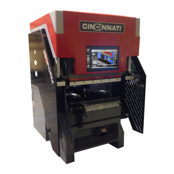
SECTION 1 IDENTIFICATION Figure 1-1 Front View 1. END GUARDING 6. EMERGENCY STOP 2. CONTROL PANEL 7. PALMBUTTONS 3. RAM 8. SAFEGUARDING DEVICE 4. RAM NOSE / DIE CLAMP 9. FILLER BLOCK (DIE HOLDER) 5. BED TOP 10. FOOTSWITCH EM 566 (R-05-17) - Page 8 Figure 1-2 Rear View 1. ELECTRICAL ENCLOSURE 5. CABINET AIR CONDITIONER 2. DRIVE ASSEMBLY (BEHIND GUARDING) 6. CONTROL ENCLOSURE 3. BACKGAGE 7. ETHERNET PORT 4. MOUNTING FEET 8. REAR GUARDING EM-566 (R-05-17)
- Page 9 Figure 1-3 Control Panel 1. CONTROL ON/OFF 5. NEXT RAM MOVEMENT UP/DOWN (TOUCH SCREEN) 2. MAIN DRIVE START 6. EMERGENCY STOP 3. MAIN DRIVE STOP 4. RAM UP EM-566 (R-05-17)
- Page 10 EM-566 (R-05-17)
-
Page 11: Section 2 Installation
INSTALLATION UNLOADING After receiving the CINCINNATI GOFORM, carefully remove the contents of the one or more boxes shipped with the machine. All of the machine’s optional accessories and small parts are in these boxes. Check all of these parts with the packing list. Any claims for shortages should be made within ten days. Remove all shipping paper from the wrapped parts of the machine. -
Page 12: Leveling
Refer to local and state codes for acceptable grounding methods. If a CINCINNATI INCORPORATED Service Representative is not present, call before proceeding any further or starting machine. Our Service Representative will complete all electrical connections and check motor rotation. -
Page 13: Section 3 Safety
The press brake, tooling, piece part and method of feed and removal must be evaluated for each job before deciding on the safeguarding to be used. See CINCINNATI Safeguarding Bulletin PI-50686 for ideas on types of safeguarding available. - Page 14 If the CINCINNATI press brake is equipped with “Point of Operation” safeguarding devices, such as a light curtain or Laser Guard, refer to Light Curtain configuration in SECTION 7 of the Operation, Safety, and Maintenance Manual. Follow the instructions given in this manual closely while installing or removing tooling from this GOFORM Electric Press Brake.
-
Page 15: Rules For Safe Operation
LOOK THINGS OVER CAREFULLY Before operating the CINCINNATI GOFORM press brake, look to see if the machine is in proper condition. Are the dies worn? Are the machine’s covers and guards securely in place? Are all nuts, bolts and screws tight? Is everything in proper operating condition? If not, report any unsafe condition or needed repair to the supervisor and be sure the problem is corrected before beginning operations. -
Page 16: Installing, Removing, And Transferring Tooling (Dies)
12. Stand clear of the workpiece with arms slightly extended to avoid being hit if the stock whips up or down as the bend is made. Be sure to know how the workpiece will react to the bend being made. If the workpiece whips up, place the thumbs and fingers below the material. -
Page 17: Safety Signs
All safety signs installed on the machine by CINCINNATI INCORPORATED are identified by a small six digit part number in the lower right corner. If any of these safety signs become damaged or defaced, new ones should be ordered by contacting the factory or the nearest CINCINNATI Sales and Service Office. - Page 18 SAFETY GUIDELINES (433727) DANGER ELECTRIC SHOCK (825742) This Safety Guidelines sign is attached to the This DANGER sign is located on the electrical panel front cover of the press brake. This sign provides near the main disconnect switch. The sign alerts the a checklist of safety considerations that should be operator and the maintenance personnel to the risk observed before, during and after operation of the...
-
Page 19: Press Brake Operator Safety Guidelines
PRESS BRAKE OPERATOR SAFETY SAFETY MAINTENANCE CHECK GUIDELINES • SAFEGUARDING at point-of-operation in proper adjustment and operating properly • Be sure to know the press brake capacity, controls, operating modes, and safeguarding. • PINCH POINT guarding properly installed • Know and understand the job about to be performed: •... - Page 20 EM-566 (R-05-17)
-
Page 21: Section 4 Specifications
SECTION 4 SPECIFICATIONS PERFORMANCE AND RATINGS SHIPPING BENDING TOTAL WEIGHT BED TOP CAPACITY CLEAR OVERALL OVERALL ABOVE MOTOR (Mild Steel) DISTANCE LENGTH FLOOR H.P. SERIES BETWEEN SURFACE WIDTH 40 GX In.-Nominal (kw) HOUSINGS Lbs. GA. x FT. (mm) Ft.-In. (m) (mm) (kg) (mm x m) - Page 22 TONNAGE The tonnage on a GOFORM Electric Press Brake is adjustable from approximately 5% of CAPACITY full tonnage to full tonnage. DIE SPACE The GOFORM Electric Press Brake has a fixed amount of die space to accommodate the dies or tooling and filler block (die Holder). OPEN HEIGHT is the maximum die space available.
-
Page 23: Section 5 Setup And Use
SECTION 5 SETUP AND USE PRESS BRAKE TOOLING The GOFORM press brake is a very versatile bending machine. It is capable of exerting high forces between its bed and ram. These forces are applied and directed into the material to be formed by the use of tooling (dies). The type and shape of the dies are the principle factors in establishing the shape of the part to be formed. -
Page 24: Types Of Dies
Do not use ANGLE mode when bottoming. Use POSITION or TONNAGE Reversal. CINCINNATI INCORPORATED can provide many other types of standard and special dies, some of which are shown in Figure 5-4. FIGURE 5-4 Types of dies... -
Page 25: Tool Installation
TOOL INSTALLATION To install the tooling, use the following procedure: 1. If the GOFORM is not already powered up, turn on the main disconnect switch on the electrical enclosure. 2. Press the “MAIN DRIVE START” button on the GOFORM PC Control. 3. - Page 26 To view other diagnostic information, such as independent left and right ram position or actual gage position, use the Maintenance | Diagnostics | Encoders/Tonnage or Maintenance | Diagnostics | Gage Positions menu items. 6. Turn the “CONTROL ON-OFF” keyswitch to “ON”. 7.
- Page 27 FIGURE 5-5 Die Positioning FIGURE 5-6 Seating Dies 16. Moderately tighten ram die clamp bolts to prevent the upper die from falling when the ram is raised. Turn “CONTROL ON-OFF” keyswitch to “ON”. 17. Press the “RAM UP” button to raise the ram .125” to .25” (3.2 to 6.4 mm). Turn the “CONTROL ON-OFF” keyswitch to “OFF”...
-
Page 28: Operating Techniques
OPERATING TECHNIQUES The following guidelines will help the operator avoid operating problems, producing bad parts, causing injury to himself or damage to the tooling or machine. TOOLING AND SETUP • DO inspect the tooling carefully before starting any job. It may be impossible to compensate for badly worn dies and they could create a safety hazard. -
Page 29: Speed Change/Forming Speed
• DO store the changes that are made to a new or old program. The latest program must be stored to save the changes. • ALWAYS block the ram or position the ram at bottom of the stroke and turn “OFF” OPERATOR CONTROLS switch and remove the key whenever leaving the machine. - Page 30 Click on the Setup Mode tab of the ‘Operator Stations’ dialog. Ensure that the Station 1 check box is checked. If it is not already checked, click on the white box to the left of the “Station 1” label to enable it. Then press the “OK”...
-
Page 31: Section 6 Machine Controls
SECTION 6 SECTION MACHINE CONTROLS TITLE PC CONTROL The Control is an industrial PC with an LCD touchscreen display integrated into the machine directly above the ram. Features of the Control include an Operator Control keyswitch and “MAIN DRIVE START” and “MAIN DRIVE STOP”... -
Page 32: Control On-Off Keyswitch
CONTROL ON-OFF KEYSWITCH This keyswitch must be turned on to allow the active operator stations to cycle the ram. In the “OFF” position, the Operator Stations are prevented from cycling the ram even though the main drive motor may be running. The ram cannot be moved with the “RAM UP” button. The operator should lock this switch off and remove the key when away from the machine or when performing adjustments to prevent... -
Page 33: Main Disconnect Switch
FOOTSWITCH The GOFORM is equipped with two footswitches. One is located on the floor and the other on the footrest. Only one footswitch can be active at a time. A cable-connected Footswitch is provided to actuate ram movement. This is a three position Operator Station which controls ram motion. The footswitch is completely enclosed to minimize inadvertent actuation of the switch. - Page 34 EM-566 (R-05-17)
-
Page 35: Section 7 Operation
FOR ADDITIONAL SETUP AND OPERATIONAL INFORMATION FOR THIS MACHINE, REFER TO EITHER THE ONLINE HELP INFORMATION THAT CAME WITH THE MACHINE SOFTWARE OR TO EM-508, SECTION 7, OPERATION – A SUPPLEMENT TO THE OPERATION MANUAL FOR THE CINCINNATI GOFORM PC CONTROL. - Page 36 EM-566 (R-05-17)
-
Page 37: Section 8 Options
UNFOLDER MODULE The CINCINNATI Unfolder Software is an option for offline use, for either CINCINNATI Laser Programming and Nesting Software or CINCINNATI Bend Simulation Software or both. The software unfolds 3D models to flat patterns and outputs directly to Nesting or BendSim. - Page 38 Reference ANSI B11.3 – 2012 for details about Close Proximity point of operation AOPD safeguarding, Safe Speed Safeguarding and three-position hold-to-run controls. WILSON EXPRESS DIE HOLDER WITH WEDGE HEIGHT ADJUSTMENT The Express Die Holder is 2.95” tall x 2.25” wide and used for lower dies with 1/2” (12.7mm) or 13mm tongues. Clamp bars are used instead of set screws to allow sectionalized dies to be clamped along the length of the bed.
-
Page 39: Lockout / Tagout Procedure
TITLE MAINTENANCE AND ADJUSTMENTS To maintain the accurate performance of the CINCINNATI GOFORM Electric Press Brake, there are maintenance practices that should be followed. This section deals with the maintenance and adjustments of the Press Brake. LOCKOUT / TAGOUT PROCEDURE This procedure only covers the typical energies of a GOFORM Electric Press Brake. -
Page 40: Checking & Adjusting The Swivel End-Guide Bearing
SET THE LEFT UPPER LIMIT SWITCH SET THE RIGHT UPPER LIMIT SWITCH The center of the proxmity switch should be at a The center of the proximity switch should be at distance of 22.25 inches from the bed top. The a distance of 26.75 inches from the bed top. -
Page 41: Lubrication
LUBRICATION 1. Ram Guides: Wipe clean and coat with Dry Moly Lube once a month. 2. Roller Screws: (Figure 9-5) Lubrication is required every 500 working hours. Relubricate Roller Screws with 14 grams of Mobilith SHC 220 Grease (CI P/N 434530) FIGURE 9-5 Roller Screw Lubrication points DO NOT use EP-2 grease to lubricate the roller screws. -
Page 42: Electrical
ELECTRICAL There are no customer serviceable parts in the main electrical enclosure. Contact a CINCINNATI INCORPORATED Service Representative for detailed information. X-AXIS MAINTENANCE X-Axis maintenance (Figure 9-7) is required every 500 hours of operation. Tracking of the required maintenance items should be accomplished using the maintenance messages screen within the press brake master software. -
Page 43: R-Axis Maintenance
R-AXIS MAINTENANCE The only action required on the R-Axis is the EMC (Electromechanical Cylinder) lubrication. Lubrication will be required every 500 hours. Tracking of the required maintenance items should be accomplished using the maintenance messages screen within the press brake master software. Go to Maintenance | Maintenance Messages to see the list of maintenance items required and their respective maintenance interval. -
Page 44: Troubleshooting
Most problems, however, can be more efficiently diagnosed by contacting a local CINCINNATI Field Service Representative or through telephone support with a Technical Service Specialist. Having the following information ready before making contact with a CINCINNATI Representative will help to diagnose the problem faster. -
Page 45: Section 10 Service And Parts
3. Service can be schedulded by calling 513-367-7100 or through email at service@e-ci.com TECHNICAL TRAINING CINCINNATI INCORPORATED offers a variety of Operator and Maintenance Training Programs to assist our customers in obtaining maximum value from the investment in metal fabricating equipment. With today’s sophisticated CNC controls, operator knowledge and proficiency have a significant effect on overall productivity. - Page 46 C O P Y R I G H T 2 0 1 7 C I N C I N N AT I I N C O R P O R AT E D Is a Registered Trademark of Cincinnati Incorporated.
Need help?
Do you have a question about the Goform 40 GX Series and is the answer not in the manual?
Questions and answers