Table of Contents
Advertisement
Quick Links
Advertisement
Table of Contents

Related Manuals for Konsberg SIMRAD Robertson RI35 Mk2


Summary of Contents for Konsberg SIMRAD Robertson RI35 Mk2
- Page 1 INSTRUCTION MANUAL Robertson RI35 Mk2 Rudder Angle Indicator 20220919...
- Page 2 NOTE! Simrad Robertson AS makes every effort to ensure that the information contained within this document is correct. However, our equipment is continuously being improved and updated, so we cannot assume liability for any errors which may occur. The information contained within this document remains the sole property of Simrad Robertson AS.
- Page 3 Instruction manual Instruction Manual This manual is intended as a reference guide for operating and correctly installing the RI35 Mk2 Rudder Angle Indicator. Please take time to read the manual to get a thorough understanding of the indicator system and its relationship to a complete autopilot system.
-
Page 4: Table Of Contents
Robertson RI35 Mk2 Rudder Angle Indicator Contents INTRODUCTION .............3 TECHNICAL SPECIFICATIONS ........3 INSTALLATION...............4 Connections.................5 Stand alone rudder angle indicator(s) .......5 Connection to autopilot junction units.......6 Use of NMEA ..............9 Panel mounting..............9 Bracket mounting ............. 10 Illumination ..............10 Zero adjust ................ 11 Autopilots with no rudder zero adjust ...... -
Page 5: Introduction
Instruction manual 1. INTRODUCTION The RI35 Mk2 is manufactured in non-corrosive aluminum with a non-reflective black finish. It is designed to operate from frequency or current signals generated by a Robertson autopilot feedback unit. It will also accept a NMEA 0183 rudder angle (RSA) signal. The indicator is made in standard modular size (132x108 mm) to match the Robertson AP35 autopilot. -
Page 6: Installation
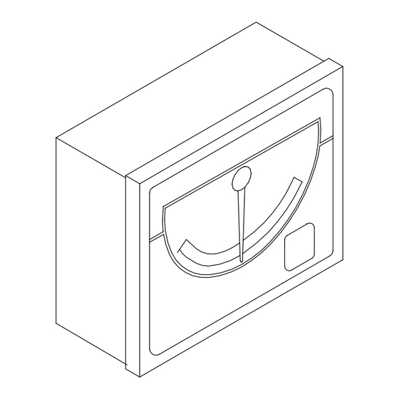
Robertson RI35 Mk2 Rudder Angle Indicator Safe distance to magnetic compass: ......0.3 m (1 ft) Cable: ........20 m, single twisted pair (not connected). Rudder Feedback Units: ..RF300 (frequency signal), RF45X (current or frequency signal), RF100 (current signal). Figure 2-1 RI35 Mk2 Dimensions 3. -
Page 7: Connections
Instruction manual 3.1 Connections Stand alone rudder angle indicator(s) RF45X Rudder Feedback Unit (Current signal) RI35 Mk2 RI3 5 Mk2 RU DDER AN GLE RUDDER AN GL E IND ICATOR INDICATOR N M E A C U R R F R E Q S U P P L Y N M E A C U R R F RE Q S U P P L Y... -
Page 8: Connection To Autopilot Junction Units
Robertson RI35 Mk2 Rudder Angle Indicator Connection to autopilot junction units The interconnection cables are screened, and the screen should be grounded in the autopilot junction unit. See Figure 3-3 through Figure 3-7 for connections to the different autopilot junction units. J3000X/J300X/J300X-40 RI35 Mk2 RI3 5 Mk2... - Page 9 Instruction manual RI35 M k2 RI35 M k2 J45A JUNCTION UNIT RUDDER AN GLE RUDDER AN GLE INDICAT OR INDICAT OR N ME A N M E A C U R R C U R R F R E Q S U PP L Y F R E Q S U PP L Y 1 2 1 1 1 0 S U PP LY VO LT AG E 1 2 / 2 4 V...
- Page 10 Robertson RI35 Mk2 Rudder Angle Indicator J101A/J200S JUNCTION UNIT RI35 Mk2 RUDDER ANGLE Use a separate terminal INDICAT OR for this connection N M E A C U R R F R E Q S U P P L Y 1 2 1 1 1 0 G R E E N G R E E N...
-
Page 11: Use Of Nmea
Instruction manual 3.2 Use of NMEA The NMEA port on the RI35 Mk2 is unidirectional, i.e. it is automatically configured for input (listening) or output (talking). The listener port is also non-polarized. For best performance, if the RI35 Mk2 is to be used with a non- Robertson rudder feedback outputting NMEA data (RSA), 20Hz is recommended. -
Page 12: Bracket Mounting
Robertson RI35 Mk2 Rudder Angle Indicator 3.4 Bracket mounting • Mount two of the bracket halves to the RI35 Mk2. • Temporarily bolt together the other two halves of the bracket to the first two halves. • Hold the RI35 Mk2 in place by hand and mark the 4 holes for the fixing screws on the mounting surface. -
Page 13: Zero Adjust
Instruction manual 3.6 Zero adjust Prior to making a zero adjustment on the indicator, make sure the Note ! feedback unit is installed and aligned according to it’s mounting instruction. Autopilots with no rudder zero adjust With the rudder amidships, the indicator should read zero. If not, adjust the pointer to zero reading by pressing and holding the illumination key for 5 (five) seconds. -
Page 14: Maintenance
Robertson RI35 Mk2 Rudder Angle Indicator If you let go of key before conformation of reversed deflection has Note ! been given, the RI35 Mk2 will think you meant to do a zero adjust and leave the pointer at zero. Then simply repeat section 3.6. 4. -
Page 15: Spare Parts
Instruction manual 6. SPARE PARTS Art. no. Description 22082929 Installation accessories 22083265 RI35 Cable 22083943 RI35 Mk2 Board assy (PCB) 22083968 RI35 Mk2 Front Panel 22084016 RI35 Mk2 Front Housing 22083992 RI35 Mk2 Back Cover 44164135 Blind plug 44140796 Cable gland 44141174 Seal (o-ring) 44140812... - Page 16 Robertson RI35 Mk2 Rudder Angle Indicator 20220919A...
Need help?
Do you have a question about the SIMRAD Robertson RI35 Mk2 and is the answer not in the manual?
Questions and answers