
Related Manuals for ACIQ ACIQ-24-ACL


Summary of Contents for ACIQ ACIQ-24-ACL
- Page 1 ACiQ DUCTED INVERTER SYSTEMS SERVICE MANUAL A-Coils: AC (Cooling-Only) Condensers: ACIQ-24-ACL ACIQ-18-AC ACIQ-36-ACL ACIQ-24-AC ACIQ-60-ACL ACIQ-30-AC ACIQ-36-AC ACIQ-48-AC Version Date: 05-13-24...
-
Page 2: Table Of Contents
Table of Contents §. Safety Precautions Precautions Information servicing §. Model Reference & External Appearance Model Reference External Appearance §. Indoor Unit-A-COIL 1. Dimensional Drawings 2. Introduction §. 24V Coil Interface 1. System Introduction 2. Main Functions of 24V Coil Interface 3. - Page 3 Table of Contents §. Maintenance §. Product Features §. Troubleshooting Safety Caution General Troubleshooting Information Inquiry Error Diagnosis and Troubleshooting Without Error Code Quick Maintenance by Error Code Troubleshooting by Error Code Check Procedures Appendix Temperature Sensor Resistance Value Table for T1,T2,T3 and T4 (°C – K) Temperature Sensor Resistance Value Table for TP(for some units) (°C –...
- Page 4 Safety Precautions Contents Precautions ......................2 Information servicing(For flammable materials) ..........3...
-
Page 5: Safety Precautions
1. Precautions CAUTION To prevent personal injury, or property or unit damage, • While unpacking be careful of sharp edges around adhere to all precautionary measures and instructions the unit as well as the edges of the fins on the con- denser and evaporator. -
Page 6: Information Servicing
2. Information servicing(For to the surrounding space. Prior to work taking place, the area around the equipment is to be surveyed to make sure flammable materials) that there are no flammable hazards or ignition risks. NO SMOKING signs shall be displayed. Checks to the area Ventilated area •... - Page 7 • that capacitors are discharged: this shall be done in a shall also take into account the effects of aging or safe manner to avoid possibility of sparking continual vibration from sources such as compressors or fans. • that there no live electrical components and wiring are exposed while charging, recovering or purging the 2.13 Detection of flammable refrigerants system;...
- Page 8 • The refrigerant charge shall be recovered into the • Before attempting the procedure ensure that: correct recovery cylinders. The system shall be flushed • mechanical handling equipment is available, if with OFN to render the unit safe. This process may required, for handling refrigerant cylinders;...
- Page 9 • Empty recovery cylinders are evacuated and, if are unaware of the procedure taking place possible, cooled before recovery occurs. • The hose must be of sufficient length and diameter • The recovery equipment shall be in good working such that it will extend to at least 3 m beyond the order with a set of instructions concerning the outside of the building equipment that is at hand and shall be suitable for the...
- Page 10 Model Reference Contents Model Reference ....................2 External Appearance .....................3...
-
Page 11: Model Reference
Refer to the following table to determine the specific indoor and outdoor unit model number of your purchased equipment. Capacity Power Indoor Unit Model Outdoor Unit Model (Btu/h) Supply ACIQ-18-AC ACIQ-24-ACL ACIQ-24-AC 1Ph, ACIQ-30-AC A-COIL ACIQ-36-ACL 208/230V~, ACIQ-36-AC 60Hz ACIQ-48-AC ACIQ-60-ACL ... -
Page 12: External Appearance
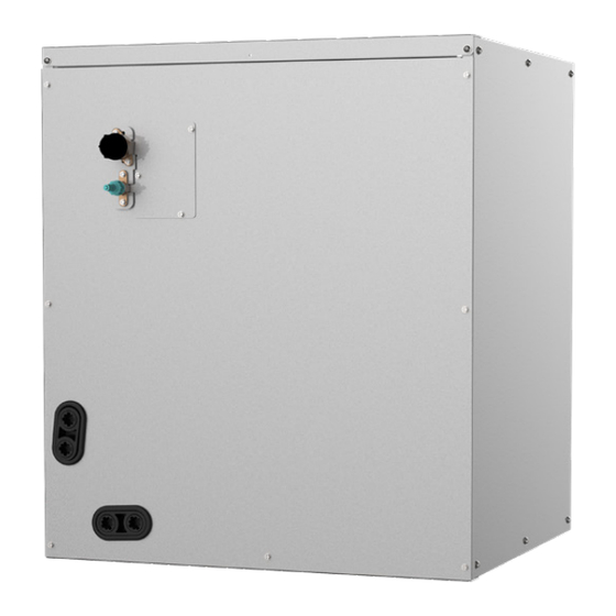
2. External Appearance Indoor Unit A-COIL Outdoor Unit Single Fan Outdoor Unit Double Fan Outdoor Unit Model Reference ... -
Page 13: Indoor Unit-A-Coil
Indoor Unit-A-COIL Contents Dimensional Drawings ..................2 Introduction ......................3... -
Page 14: Dimensional Drawings
1. Dimensional Drawings 18k/24k 30k/36 Dimensions Old panel style Old panel style Old panel style New panel style Model inch inch inch inch Model Height Model Width 17-1/2 24-1/2 Supply Air Opening Width 16-3/16 19-3/4 23-1/4 19-3/4 Return Air Opening Width 15-1/8 19-1/2 19-1/2... -
Page 15: Introduction
2. Introduction Use this instruction manual to install indoor coil on multipose furnaces. The coil is enclosed in a casing. For 18k~48k Supply Return Horizontal Left Furnace Installation Evaporator Coil Return Supply Horizontal Right Furnace Installation Supply Return Down ow Furnace Evaporator Installation... - Page 16 For 60k, Supply Return Horizontal Left Furnace Installation Evaporator Coil Return Supply Horizontal Right Furnace Installation Supply Return Down ow Furnace Installation Evaporator Coil Up ow Furnace Installation Supply Return Typical Coil Installation on Furnace IDU-A-COIL 4 ...
- Page 17 24V Coil Interface Contents 1. System Introduction ..................2 2. Main Functions ....................3 3. Ensure You Have The Following Parts ............3 4. Dimensions ....................4 5. Wiring Diagram ..................... 4 6. Dip Switch Definitions .................. 5 7. Control Signals To The Furnace ..............8 8.
-
Page 18: System Introduction
1. System Introduction (1) (2) (1). A-COIL (2). Pipe temperature sensor(T2) (3). Drain pan (4). Condensate drain connection (5). Furnace (6). Indoor and outdoor unit communication cable (7). Power supply system (8). 24V coil interface (9). Wired wall controller (10). Room temperature sensor(T1) NOTE: The 1/2-inch wiring holes on the box needs to be connected to standard conduit tting and conduit ( exible or rigid). -
Page 19: Main Functions
2. Main Functions Of 24V Coil Interface (1) Communicates the difference in space temperature and space setpoint temperature to the control that sets compres- sor speed (2) Provides a signal to the indoor fan to set fan speed appropriate for compressor staging Features •... -
Page 20: Dimensions
4. Dimensions 188.0mm (7.40”) 213.0mm (8.39”) 260.0mm (10.23”) 344.0mm 57.0mm (13.54”) (2.24”) 5. Wiring Diagram WIRING DIAGRAM NOTE1: CODE PART NAME 1.The parts with dotted line indicates 24V THERMOSTATS SETTING optional features. ROOM TEMP.SENSOR 2.Remove the short connector of JR1 COIL TEMP.SENSOR when you use the "on-off"... -
Page 21: Dip Switch Definitions
6. DIP Switch Definitions FOR SETTING NETADDRESS S1+S2 CODE 0~15 16~31 32~47 48~63 NETADDRESS F A C T O R Y S E T T I N G A. Micro-switch S1 and dial-switch S2 are for address setting when you want to control this unit by a central controller. Range: 00-63 Network address: The address silkscreen is NET address, which is composed of a 16-bit address rotary code S2 plus a two-digit DIP switch S1 [Set during engineering installation, no network function does not need to be set]... - Page 22 24V THERMOSTATS SETTING 1 2 3 1 2 3 1 2 3 1 2 3 CODE ON~OFF ON~OFF ON~OFF ON~OFF ON~OFF FACTORY SETTI SW4 is unused. C:Function DIP switch settings: Dial code Function OFF(Default) Note Control Scenario 24V Tstat, S1+S2 SW1-2 Anti-cold blow protection option [Default] Yes...
- Page 23 Control Scenario Wired Controller S1+S2 SW1-2 Anti-cold blow protection option [Default] Yes Single cooling / heating and SW1-3 Cooling [Default] Cooling & Heating cooling options The operation of heat [Default] Only one heat pump is limited by the pump or auxiliary heat can be outdoor temperature, and operated .The system makes the operation of auxiliary...
-
Page 24: Control Signals To The Furnace
7. Control Signals To The Furnace Control signals to the furnace are the standard thermostat control signals R,C,W1,W2,Y2 and Y1. Connector Usage Provides 24VAC power from the furnace to the board. The 24VAC common wire between the furnace and the board. First stage of furnace command line from the board to the furnace. -
Page 25: Electrical Characteristics
8. Electrical Characteristics Capacity (Btu/h) Phase Power (indoor) Frequency And Volt 208/230V,60Hz Phase Power (Outdoor) Frequency And Volt 208/230V,60Hz Indoor unit(A) Max. Fuse Outdoor unit(A) Indoor unit Line quantity Line diameter(AWG) 16/1.5mm² 16/1.5mm² 16/1.5mm² Power line Outdoor unit Line quantity Line diameter(AWG) 12/4.0mm²... - Page 26 Outdoor Unit Contents Dimensional Drawings ..................2 Service Place ......................19 Capacity Correction Factor for Height Difference ..........20 Noise Criterion Curves ..................23 Refrigerant Cycle Diagrams ................25 Electrical Wiring Diagrams ..................26...
-
Page 27: Dimensional Drawings
1. Dimensional Drawings Please check the corresponding dimensional drawing according to the panel plate. Outdoor Unit Model Panel Plate ACIQ-18-AC X330 ACIQ-24-AC ACIQ-30-AC ACIQ-36-AC ACIQ-48-AC Outdoor Unit 2 ... - Page 28 Panel Plate X230 (Rounded grille 1) Outdoor Unit 3 ...
- Page 29 Panel Plate X230 (Rounded grille 2) Outdoor Unit 4 ...
- Page 30 Panel Plate X230(Square grille) Outdoor Unit 5 ...
- Page 31 X330(Rounded grille 1) Panel Plate Outdoor Unit 6 ...
- Page 32 X330(Rounded grille 2) Panel Plate Outdoor Unit 7 ...
- Page 33 X330(Square grille) Panel Plate Outdoor Unit 8 ...
- Page 34 X430(Rounded grille 1) Panel Plate Outdoor Unit 9 ...
- Page 35 X430(Rounded grille 2) Panel Plate Outdoor Unit 10 ...
- Page 36 X430(Square grille) Panel Plate Outdoor Unit 11 ...
- Page 37 Panel Plate D30(Rounded grille 1) Outdoor Unit 12 ...
- Page 38 Panel Plate D30(Rounded grille 2) Outdoor Unit 13 ...
- Page 39 Panel Plate D30(Square grille) Outdoor Unit 14 ...
- Page 40 Panel Plate X630(Square grille) Outdoor Unit 15 ...
- Page 41 Panel Plate E30(Square grille) Outdoor Unit 16 ...
- Page 42 Panel Plate E30(Rounded grille 1) Outdoor Unit 17 ...
- Page 43 Panel Plate E30(Rounded grille 2) Outdoor Unit 18 ...
-
Page 44: Service Place
2. Service Place Outdoor Unit 19 ... -
Page 45: Capacity Correction Factor For Height Difference
3. Capacity Correction Factor for Height Difference Capacity(Btu/h) 6k~9k Pipe Length (m/ft) Cooling 7.5/24.6 10/32.8 20/65.6 25/82 10/32.8 0.969 0.936 0.920 Indoor Upper than Outdoor 5/16.4 0.995 0.979 0.946 0.929 Height difference 1.000 0.984 0.951 0.934 H (m) -5/-16.4 1.000 0.984 0.951 0.934... - Page 46 Capacity Pipe Length (m/ft) (Btu/h) Cooling 7.5/24.6 10/32.8 20/65.6 30/98.4 40/131.2 50/164 25/82 0.891 0.862 0.832 20/65.6 0.930 0.900 0.871 0.841 Indoor Upper than Outdoor 10/32.8 0.970 0.940 0.910 0.879 0.849 Height 5/16.4 0.995 0.980 0.949 0.919 0.888 0.858 difference 1.000 0.985 0.954...
- Page 47 Capacity Pipe Length (m/ft) (Btu/h) Cooling 7.5/24.6 15/49.2 25/82 35/114.8 50/164 65/213.3 30/98.4 0.870 0.823 0.775 20/65.6 0.911 0.879 0.831 0.783 Indoor Upper than Outdoor 10/32.8 0.953 0.920 0.888 0.840 0.791 5/16.4 0.995 0.962 0.930 0.897 0.848 0.799 Height difference 1.000 0.967 0.934...
-
Page 48: Noise Criterion Curves
4. Noise Criterion Curves 1.0m/3.28ft Note: H= 0.5 × height of outdoor unit Notes: -Sound measured at 1.0m/3.25ft away from the center of the unit. -Data is valid at free field condition -Data is valid at nominal operation condition -Reference acoustic pressure OdB=20µPa -Sound level will vary depending on arrange off actors such as the construction (acoustic absorption coefficient) of particular room in which the equipment is installed. - Page 49 ACIQ-18-AC ACIQ-24-AC ACIQ-30-AC ACIQ-48-AC ACIQ-36-AC Outdoor Unit 24 ...
-
Page 50: Refrigerant Cycle Diagrams
5. Refrigerant Cycle Diagrams Pipe Size (Diameter:ø) Piping length (m/ft) Elevation (m/ft) mm(inch) Model Additional Refrigerant Liquid Rated Max. Rated Max. ACIQ-18-AC 19(3/4) 9.52(3/8) 7.5/24.6 30/98.4 20/65.6 ACIQ-24-AC 19(3/4) 9.52(3/8) 7.5/24.6 50/164 25/82 ACIQ-30-AC 19(3/4) 9.52(3/8) 7.5/24.6 50/164 25/82 65g/m (0.69oz/ft) -
Page 51: Electrical Wiring Diagrams
6. Electrical Wiring Diagrams ODU Model ODU Wiring Diagram ACIQ-18-AC 16022000039590 ACIQ-24-AC 16022000039430 ACIQ-30-AC 16022000039410 ACIQ-36-AC ACIQ-48-AC 16022000039411 ODU Main Printed Circuit Inverter Module ODU Model 24V Printed Board Board Printed Board ACIQ-18-AC 17122000048066 ACIQ-24-AC 17122000048064 ACIQ-30-AC 17122000054047 17122000047742 ACIQ-36-AC... - Page 56 Outdoor unit printed circuit board diagram: 17122000048064& 17122000048066 RC 2 VU B...
- Page 57 Name Meaning Earth: connect to Ground Power Supply N_in: connect to N-line (208-230V AC input) L_in: connect to L-line (208-230V AC input) S: connect to indoor unit communication 4-WAY CN60 connect to 4 way valve, 208-230V AC when is ON. AC-FAN connect to AC fan HEAT2...
- Page 58 Outdoor unit printed circuit board diagram: 17122000047742...
- Page 59 Name Meaning CN11 N_in: connect to N-line (208-230V AC input) Power Supply CN12 L_in: connect to L-line (208-230V AC input) EEV-A CN16 EEV-B CN13 EEV-C EEV-D CN15 connect to electric expansion valve EEV-E EEV-F CN17 EEV-G CN14 connect to pipe temp. sensor T3, ambient temp. sensor T4, exhaust T3 T4 TP CN26 temp.
- Page 60 Name Meaning HEAT_D CN20 connect to the heater, 208-230V AC when is ON CN21 HEAT_Y CN36 4-WAY CN38 connect to 4 way valve, 208-230V AC when is ON. CN27 connect to key board CN1 Note: This section is for reference only. Please take practicality as standard.
- Page 61 Outdoor unit printed circuit board diagram: 17122000037804...
- Page 62 Name Meaning L1_in: connect to L1-line (230V AC input) Power Supply L2_in: connect to L2-line (230V AC input) Exhaust temp. sensor TP TESTPORT CN35 used for testing HEAT1 CN19/CN20 connect to chassis heater, 208-230V AC when is ON HEAT2 CN24/CN25 connect to compressor heater, 208-230V AC when is ON 4-WAY CN17/CN18...
- Page 63 Outdoor unit IPM board diagram: 17122000042012...
- Page 64 Name Meaning connect to main board L-Out Power Supply connect to main board N-Out connect to main board CN6 FAN_DC FAN_1/FAN_2 connect to outdoor DC fan 1& DC fan 2 CN_COMP connect to compressor Note: This section is for reference only. Please take practicality as standard.
- Page 65 Outdoor unit printed circuit board diagram: 17122000054047...
- Page 66 Name Meaning connect to one-way solenoid valve connect to pressure sensor (5VDC) CN28 connect to electric expansion valve (12VDC) TESTPORT CN45 used for testing (5VDC) connect to suction temp. sensor, cold plate temp. sensor CN11 (5VDC) H-PRO CN38 connect to high pressure switch (5VDC) connect to main board L-Out Power Supply connect to main board N-Out...
- Page 67 Installation Contents Installation Overview Location Selection Indoor Unit Installation Outdoor Unit Installation Drainage Pipe Installation Refrigerant Pipe Installation Vacuum Drying and Leakage Checking Additional Refrigerant Charge Engineering of Insulation Engineering of Electrical Wiring Test Operation...
-
Page 68: Installation Overview
1. Installation Overview Indoor Unit Indoor Unit Install the indoor unit Install the outdoor unit Install the drainpipe Evacuate the refrigeration system Connect the wires Connect the refrigerant pipes Perform a test run 1. Installation Overview ... -
Page 69: Location Selection
2. Location selection 2.1 Unit location selection can refer to installation manual. 2.2 DO NOT install the unit in the following locations: • Where oil drilling or fracking is taking place. • Coastal areas with high salt content in the air. •... -
Page 70: Indoor Unit Installation
3. Indoor Unit Installation(A-COIL) Horizontal Right Installation 3.1 Install evaporator coils 1. Use field fabricated attachment plates to secure coil to furnace. Upflow coil installation 2. Use self-tapping screws to mount attachment plates to The cased coil is designed to ft furnaces of the same coil casing. - Page 71 New style Old style Ductwork Air ow Furnace 4"minimum 4"minimum 4" Furnace Ductwork Air ow Vertical Upfow & Downfolw Installation Old style 4"minimum Downflow Installation with Coil Rotated 90° New style Furnace Coil Ductwork Air ow 4"minimum Furnace Coil Air ow Ductwork Horizontal Right &...
- Page 72 3.2 Installation of the 24V Coil Interface 4.After the wiring is complete, reattach the cover, being sure not to pinch any wiring and tightening the 4 1.Remove the cover of 24V coil interface by removing all attachment screws. Cover 24V coil interface lid, locking 4 exposed screws with a phillips head screwdriver.
-
Page 73: Outdoor Unit Installation
4. Outdoor unit installation 2. Connect a drain hose extension (not included) to the drain joint to redirect water from the unit during heating 4.1 Service space for outdoor unit mode. 4.3 Bolt pitch Panel Plate Unit 4.2 Install drain joint(Heat pump unit only) inch 11.93 17.80... - Page 74 4.4 Install Outdoor Unit Fix the outdoor unit with anchor bolts(M10) >60cm / 23.6” Fix with bolts Caution Since the gravity center of the unit is not at its physical center, so please be careful when lifting it with a sling. Never hold the inlet of the outdoor unit to prevent it from deforming.
- Page 75 supplied, external condensate pan should be installed 5. Condensate Drain Line Connection underneath the entire unit, and a secondary condensate line (with appropriate trap) should be run from the unit CAUTION: into the pan. Any condensate in this external condensate Failure to follow this caution may result in property pan should be drained to a noticeable place.
-
Page 76: Refrigerant Pipe Installation
2.Confirm the cross way of the pipes. 6. Refrigerant Pipe Installation 3.Measure the necessary pipe length. 6.1 Maximum length and drop height 4.Cut the selected pipe with pipe cutter Ensure that the length of the refrigerant pipe, the number • Make the section flat and smooth. -
Page 77: Vacuum Drying And Leakage Checking
7. Vacuum Drying and Leakage 10. Set the wall conduit Checking 11. Set the supporter for the pipe. 12. Locate the pipe and fix it by supporter 7.1 Purpose of vacuum drying • For horizontal refrigerant pipe, the distance be- •... -
Page 78: Additional Refrigerant Charge
4. Rain water might penetrate into pipeline during 8. Additional Refrigerant Charge construction. • After the vacuum drying process is carried out, the additional refrigerant charge process need to be performed. Procedures of special vacuum drying are as follows: • The outdoor unit is factory charged with refrigerant. -
Page 79: Engineering Of Insulation
9 . Engineering of Insulation insulation and cause easy aging of the material. 9.2 Insulation of drainage pipe 9.1 Insulation of refrigerant pipe 1. Operational procedure of refrigerant pipe 1. Operational procedure of refrigerant pipe insulation insulation Select the suitable pipe → insulation (except joint section) Cut the suitable pipe →... -
Page 80: Engineering Of Electrical Wiring
2. 24V coil interface wiring diagram Engineering of Electrical Wring 1. Highlights of electrical wiring installation • All field wiring construction should be finished by qualified electrician. • Air conditioning equipment should be grounded ac- cording to the local electrical regulations. •... -
Page 81: Test Operation
b. Turn on the main power switch and run the air 11. Test Operation conditioner in COOL mode. 1. The test operation must be carried c. Check to see that the water is discharged. It may out after the entire installation has been take up to one minute before the unit begins to drain completed. - Page 82 Maintenance Contents First Time Installation Check .................2 Refrigerant Recharge ....................4 Re-Installation .......................5 Indoor Unit ....................5 Outdoor Unit ....................7...
-
Page 83: First Time Installation Check
1. First Time Installation Check Air and moisture trapped in the refrigerant system affects To prevent air and moisture from affecting the air the performance of the air conditioner by: conditioner’s performance, the indoor unit, as well as the pipes between the indoor and outdoor unit, must be be •... - Page 84 Procedure: • If the pressure successfully reaches -0.1 MPa Tighten the flare nuts of the indoor and outdoor (14.5 Psi), fully close the Handle Lo valve, then units, and confirm that both the 2- and 3-way valves cease vacuum pump operations. are closed.
-
Page 85: Refrigerant Recharge
2. Refrigerant Recharge mA A Procedure: Close both 2- and 3-way valves. 3-way valves. Slightly connect the Handle Lo charge hose to the Operate the air conditioner in cooling mode to charge 3-way service port. the system with liquid refrigerant. Connect the charge hose to the valve at the bottom When the electronic scale displays the correct of the cylinder. -
Page 86: Re-Installation
3. Re-Installation Indoor Unit Collecting the refrigerant into the outdoor unit Procedure: Confirm that the 2- and 3-way valves are opened. Close the 3-way valve so that the gauge rests between 0.3 MPa (43.5 Psi) and 0.5 MPa (72.5 Psi). Connect the charge hose with the push pin of Handle Lo to the 3-way valve’s gas service port. - Page 87 Air purging with vacuum pump Procedure: • If the pressure successfully reaches -0.1 MPa Tighten the flare nuts of the indoor and outdoor (14.5 Psi), fully close the Handle Lo valve, then units, and confirm that both the 2- and 3-way valves cease vacuum pump operations.
-
Page 88: Outdoor Unit
Outdoor Unit Evacuation for the whole system Procedure: Wait for 5 minutes then check whether the gauge Confirm that the 2- and 3-way valves are opened. needle moves after turning off the vacuum pump. If Connect the vacuum pump to the 3-way valve’s the gauge needle moves backward, check whether service port. - Page 89 Refrigerant charging mA A Procedure: Close both 2- and 3-way valves. Fully open the Handle Lo manifold valve, 2- and 3-way valves. Slightly connect the Handle Lo charge hose to the 3-way service port. Operate the air conditioner in cooling mode to charge the system with liquid refrigerant.
- Page 90 Product Features Contents Display Function ....................2 Safety Features ......................3 Basic Functions .......................3 Abbreviation ....................3 Fan Mode ......................3 Cooling Mode ....................3 Auto Mode ....................4 Drying Mode ....................4 Forced Operation Function ................4 Timer Function ....................5 Sleep Function ....................5...
-
Page 91: Display Function
1. Display Function Mode Priority Y/Y2 W W1 W2 E/AUX DH/DS/BK Display Shut down Cooling 1 Cooling 2 Drying 1 Drying 2 Heating 1 Heating 2 Heating 2 Emergency heating Emergency heating Emergency heating Emergency heating Emergency heating Emergency heating Emergency heating Emergency heating Emergency heating... -
Page 92: Safety Features
2. Safety Features turbo and auto. • Auto fan: In fan-only mode, AC operates the same as Compressor three-minute delay at restart auto fan in cooling mode with the temperature set at 24°C(75°F). Compressor functions are delayed for up to ten seconds upon the first startup of the unit, and are delayed for up •... -
Page 93: Auto Mode
Auto Mode fan speed increases to turbo. 3.3.3 Outdoor Fan Control • This mode can be selected with the remote controller and the temperature setting can be adjusted between • The outdoor unit will be run at different fan speed 16°C~30°C. -
Page 94: Timer Function
Timer Function • The timing range is 24 hours. • Timer On. The machine turns on automatically at the preset time. • Timer Off. The machine turns off automatically at the preset time. • Timer On/Off. The machine turns on automatically at the preset On Time, and then turns off automatically at the preset Off Time. - Page 95 Troubleshooting Contents 1. Safety Caution ..................... 3 2. General Troubleshooting ................4 Error Display (Indoor Unit) ..................4 Error Display on Two Way Communication Wired Controller ........5 Error Display (For Outdoor Unit) ................6 3. Outdoor Unit Point Check Function ............7 4.
- Page 96 Troubleshooting Contents protection)/PC 11(Outdoor unit main control board DC bus high voltage protection)/PC 12(Outdoor unit main control board DC bus high voltage protection /341 MCE error) Diagnosis and Solution ......................31 PC 04(Inverter compressor drive error Diagnosis and Solution) ........32 7.10 PC 03/PC 31(Low Pressure Protection Diagnosis and Solution) ........
-
Page 97: Safety Caution
1. Safety Caution WARNING Be sure to turn off all power supplies or disconnect all wires to avoid electric shock. While checking indoor/outdoor PCB, please equip oneself with antistatic gloves or wrist strap to avoid damage to the board. WARNING Electricity remains in capacitors even when the power supply is off. -
Page 98: General Troubleshooting
2. General Troubleshooting Error Display (Indoor Unit) When the indoor unit encounters a recognized error, the operation lamp will flash in a corresponding series, the timer lamp may turn on or begin flashing, and an error code will be displayed. These error codes are described in the following table: Display Error Information... -
Page 99: Error Display On Two Way Communication Wired Controller
Low ambient temperature protection TS42 PC 0L Mismatch between the new and old platforms TS49 FL 09 For other errors: The display board may show a garbled code or a code undefined by the service manual. Ensure that this code is not a temperature reading. -
Page 100: Error Display (For Outdoor Unit)
Error Display (For Outdoor Unit) Display Malfunction or Protection Solution Outdoor EEPROM malfunction TS23 EC 51 Indoor / outdoor units communication error TS24 EL 01 Communication malfunction between adapter board and outdoor main board TS49 EL 16 IPM module protection TS30 PC 00 Top temperature protection of compressor or High temperature protection of IPM module... -
Page 101: Outdoor Unit Point Check Function
3. Outdoor Unit Point Check Function • A check switch is included on the outdoor PCB. • Push SW1 to check the unit’s status while running. The digital display shows the following codes each time the SW1 is pushed. Number of Display Remark Presses... - Page 102 Frequency limit caused by The display value is Bit7 IGBT radiator a hex number. For example, the digital Bit6 Reserved display show 2A, the Bit5 Reserved corresponding binary Frequency limit caused by low Bit4 is 101010, so Bit5=1, temperature of T2.(LH00) Frequency limit caused by Bit3=1, and Bit1=1.
-
Page 103: Engineering Mode
4. Engineering Mode Information Inquiry In order to enter to the engineering mode, and check the data of the system (data checking mode), Please make the following steps: • Make sure that the AC is on the standby status, or working normally in a non-locked conditions. •... - Page 104 Please note that: 1-The Channel number indicates a certain parameter value (Check the below table). 2-The indoor unit display will show the code for 2s, and then the parameter value. 3-In the engineering mode, the other keys or operations are invalid except for the following buttons “Power”, “Up”, “Down”...
- Page 105 Water-level alarm malfunction EH 0E Intelligent eye malfunction EH OF Communication malfunction between indoor unit and auto-lifting panel FH 07 IPM malfunction or IGBT over-strong current protection PC 00 Over low voltage protection PC 10 Over voltage protection PC 11 DC voltage protection PC 12 Top temperature protection of compressor or High temperature protection of IPM module...
-
Page 106: Advanced Function Setting
Advanced Function Setting In order to enter to the engineering mode, and check the advanced function settings, Please make the following steps: If you want to check the current functions set value (Presetting Page): 1- Firstly, you need to disconnect the power supply from the unit, and wait for 1 minute. 2- Then connect the power supply again to the unit (the unit should be under the standby state). - Page 107 Channel Function Parameter Value Meaning Remark Nothing to set 0 – Inactive Auto-restart function 1 – Active 1- Fan stop 2 - Fan runs at lowest RPM 3 - Fan runs at setting RPM 4 - Fan stops for 4 mins and runs for 1mins 5 - Fan stops for 8 mins and runs for 1mins 6 - Fan stops for 16 mins and runs for 1mins 7 - Fan stops for 24 mins and runs for 1mins...
- Page 108 Nothing to set Without limitation Cooling temperature -3.0, -2.5, -2.0, …, 3.0, 3.5, -- (Cancel) compensation Heating temperature -6.5, -6.0, -5.5, …, 0.5, 1.0, 1.5, …, 7.0, 7.5, -- (Cancel) compensation Reserved Nothing to set Reserved Nothing to set Reserved Nothing to set Reserved Nothing to set...
-
Page 109: Error Diagnosis And Troubleshooting Without Error Code
5. Error Diagnosis and Troubleshooting Without Error Code WARNING Be sure to turn off unit before any maintenance to prevent damage or injury. Remote maintenance SUGGESTION: When troubles occur, please check the following points with customers before field maintenance. Problem Solution Unit will not start TS17 - TS18... -
Page 110: Field Maintenance
Field maintenance Problem Solution Unit will not start TS19 - TS20 Compressor will not start but fans run TS19 - TS20 Compressor and condenser (outdoor) fan will not start TS19 - TS20 Evaporator (indoor) fan will not start TS19 - TS20 Condenser (Outdoor) fan will not start TS19 - TS20 Unit runs, but shortly stops... - Page 111 Troubleshooting 17 ...
- Page 112 1.Remote Maintenance Others Possible causes of trouble Unit will not start The power switch is on but fans will not start ☆ The temperature on the display board cannot be set Unit is on but the wind is not cold(hot) Unit runs, but shortly stops The unit starts up and stops frequently ☆...
- Page 113 2.Field Maintenance Refrigerant Circuit Others Possible causes of trouble Unit will not start Compressor will not start but fans run ☆ Compressor and condenser (outdoor) fan will not start Evaporator (indoor) fan will not start Condenser (Outdoor) fan will not start Unit runs, but shortly stops ☆...
- Page 114 2.Field Maintenance Electrical Circuit Possible causes of trouble Unit will not start ☆ ☆ ☆ ☆ ☆ ☆ Compressor will not start but fans run ☆ ☆ ☆ ☆ ☆ Compressor and condenser (outdoor) fan will not start ☆ ☆ ☆...
-
Page 115: Quick Maintenance By Error Code
6. Quick Maintenance by Error Code If you do not have the time to test which specific parts are faulty, you can directly change the required parts according the error code. You can find the parts to replace by error code in the following table. Error Code Part requiring replacement... - Page 116 Part requiring EL 16 eh 0b pc 06 pc 08/44/ 49 pc 0a pc 0f replacement Indoor PCB Outdoor PCB Outdoor fan motor T3 Sensor TP Sensor Pressure sensor Reactor Compressor IPM module board Data adapter board High pressure valve assy High pressure protector Low pressure protector Additional refrigerant...
-
Page 117: Troubleshooting By Error Code
7. Troubleshooting by Error Code EH 00 / EC 51 (EEPROM Parameter Error Diagnosis and Solution) Description: Indoor or outdoor PCB main chip does not receive feedback from EEPROM chip. Recommended parts to prepare: • Indoor PCB • Outdoor PCB Troubleshooting and repair: Shut off the power supply and turn it on 2 minutes later. -
Page 118: El 01 (Indoor And Outdoor Unit Communication Error Diagnosis And Solution)
EL 01 (Indoor and Outdoor Unit Communication Error Diagnosis and Solution) Description: Indoor unit can not communicate with outdoor unit Recommended parts to prepare: • Signal wires • Magnet ring • Indoor PCB • Outdoor PCB Troubleshooting and repair: Power off, then restart the unit 2 minutes later Check whether there’s any interference. -
Page 119: Eh 03 / Ec 07 (Fan Speed Is Operating Outside Of Normal Range)/Ec
EH 03 / EC 07 (Fan Speed Is Operating Outside of Normal Range)/EC 71(Over Current Failure of Outdoor DC Fan Motor)/ EC73(Zero-speed failure of outdoor DC fan motor) Diagnosis and Solution Description: When indoor / outdoor fan speed keeps too low or too high for a certain time, the unit ceases operation and the LED displays the failure. - Page 120 Index: 1. Indoor DC Fan Motor(control chip is in fan motor) Power on and when the unit is in standby, measure the voltage of pin1&pin2 of CN15, pin3 of CN34 in fan motor connector. If the value of the voltage is not in the range showing in below table, the PCB must has problems and need to be replaced.
-
Page 121: Eh 60/Eh 61/ Ec 53/Ec 52/Ec 54/Ec 56/Ec 57/Ec 50/Ec 5C (Open Circuit Or Short Circuit Of Temperature Sensor Diagnosis And Solution)
EH 60/EH 61/ EC 53/EC 52/EC 54/EC 56/EC 57/EC 50/EC 5C (Open Circuit or Short Circuit of Temperature Sensor Diagnosis and Solution) Description: If the sampling voltage is lower than 0.06V or higher than 4.94V, the LED displays the failure. Recommended parts to prepare: •... -
Page 122: El 0C (System Lack Refrigerant Diagnosis And Solution)
EL 0C (System lack refrigerant Diagnosis and Solution) Description: Judging the abnormality of the refrigeration system according to the number of compressor stops and the changes in operating parameters caused by excessive exhaust temperature. Recommended parts to prepare: • Indoor PCB •... -
Page 123: Eh 0E(Water-Level Alarm Malfunction Diagnosis And Solution)
EH 0E(Water-Level Alarm Malfunction Diagnosis and Solution) Description: If the sampling voltage is not 5V, the LED displays the failure code. Recommended parts to prepare: • Connection wires • Water-level switch • Indoor PCB Power off, then restart the unit 2 minutes later. -
Page 124: Pc 00(Ipm Malfunction Or Igbt Over-Strong Current Protection Diagnosis And Solution)
PC 00(IPM malfunction or IGBT over-strong current protection Diagnosis and Solution) Description: When the voltage signal the IPM sends to the compressor drive chip is abnormal, the display LED shows “PC 00” and the AC turn off. Recommended parts to prepare: •... -
Page 125: Pc 01(Over Voltage Or Too Low Voltage Protection)/Pc
PC 01(Over voltage or too low voltage protection)/PC 10(Outdoor unit low AC voltage protection)/PC 11(Outdoor unit main control board DC bus high voltage protection)/PC 12(Outdoor unit main control board DC bus high voltage protection /341 MCE error) Diagnosis and Solution Description: Abnormal increases or decreases in voltage are detected by checking the specified voltage detection circuit. -
Page 126: Pc 04(Inverter Compressor Drive Error Diagnosis And Solution)
PC 04(Inverter compressor drive error Diagnosis and Solution) Description: An abnormal inverter compressor drive is detected by a special detection circuit, including communication signal detection, voltage detection, compressor rotation speed signal detection and so on. Recommended parts to prepare: • Connection wires •... -
Page 127: Pc 03/Pc 31(Low Pressure Protection Diagnosis And Solution)
7.10 PC 03/PC 31(Low Pressure Protection Diagnosis and Solution) Description: If the sampling voltage is not 5V, the LED displays a failure code. Recommended parts to prepare: • Connection wires • Low pressure protector • Indoor fan assembly • Outdoor PCB Troubleshooting and repair: Low pressure protection Low pressure protection... -
Page 128: Pc 02/Lc 06(Top Temperature Protection Of Compressor Or High Temperature Protection Of Ipm Module Diagnosis And Solution)
7.11 PC 02/LC 06(Top temperature protection of compressor or High temperature protection of IPM module diagnosis and solution) Description: For some models with overload protector, If the sampling voltage is not 5V, the LED will display the failure. If the temperature of IPM module is higher than a certain value, the LED displays the failure code. Models without overload protector should be diagnosed according to the second flowchart. -
Page 129: Ec 0D(Outdoor Unit Malfunction Diagnosis And Solution)
Check the fastening screws on the PCB and IPM radiator. Replace the outdoor Are they fixed tightly? control PCB. Tighten the screws and apply silicon grease. 7.12 EC 0d(Outdoor unit malfunction Diagnosis and Solution) Description: The indoor unit detect the outdoor unit is error. Recommended parts to prepare: •... -
Page 130: Pc 40(Communication Error Between Outdoor Main Pcb And Ipm Board Diagnosis And Solution)
7.13 PC 40(Communication error between outdoor main PCB and IPM board diagnosis and solution) Description: The main PCB cannot detect the IPM board. Recommended parts to prepare: • Connection wires • IPM board • Outdoor main PCB • Electric control box Troubleshooting and repair: Is there at least one LED in the compressor driven chip light? -
Page 131: Pc 08(Current Overload Protection)/Pc 44(Outdoor Unit Zero Speed Protection)/ Pc
7.14 PC 08(Current overload protection)/PC 44(Outdoor unit zero speed protection)/ PC 46(Compressor speed has been out of control)/PC 49(Compressor overcurrent failure) diagnosis and solution Description: An abnormal current rise is detected by checking the specified current detection circuit. Recommended parts to prepare: •... - Page 132 Was the protection activated in standby? Is the power voltage is Restart the unit when the power normal? supply returns to normal Is outdoor terminal voltage Is the power wiring Reconnect the normal? wired correctly? power wiring Is the voltage between L and Are L and N wired Reconnect L and N N is normal?...
-
Page 133: Pc 0F ( Pfc Module Protection Diagnosis And Solution)
7.15 PC 0F PFC module protection diagnosis and solution) Description: When the voltage signal that IPM send to compressor drive chip is abnormal, the LED displays the failure code and the AC turns off. Recommended parts to prepare: • Connection wires •... -
Page 134: Ec 72 (Lack Phase Failure Of Outdoor Dc Fan Motor Diagnosis And Solution)
7.16 EC 72 (Lack phase failure of outdoor DC fan motor diagnosis and solution) Description: When the three-phase sampling current of the DC motor is abnormal, especially when the current of one or more phases is always small and almost 0, the LED displays the failure code. Recommended parts to prepare: •... -
Page 135: Pc 43 (Outdoor Compressor Lack Phase Protection Diagnosis And Solution)
7.17 PC 43 (Outdoor compressor lack phase protection diagnosis and solution) Description: When the three-phase sampling current of the compressor is abnormal, especially when the current of one or more phases is always small and almost 0, the LED displays the failure code Recommended parts to prepare: •... -
Page 136: Pc 45 (Outdoor Unit Ir Chip Drive Failure) Diagnosis And Solution
7.18 PC 45 (Outdoor unit IR chip drive failure) diagnosis and solution Description: When the IR chip detects its own parameter error, the LED displays the failure code when power on. Recommended parts to prepare: • Inverter module PCB. Troubleshooting and repair: Power off,then restart the unit 2 minutes later. -
Page 137: Ec55 (Outdoor Ipm Module Temperature Sensor Fault) Diagnosis And Solution
7.20 EC55 (Outdoor IPM module temperature sensor fault) diagnosis and solution Description: If the sampling voltage is 0V or 5V, the LED displays the failure code. Recommended parts to prepare: • IPM module PCB • Connection wires • Sensors • Outdoor main PCB Troubleshooting and repair: If the radiator has no sensor, follow the steps below to resolve, Power off, then restart the unit after 2 minutes. -
Page 138: Pc 03/Pc 30 (High Pressure Protection Diagnosis And Solution)
7.21 PC 03/PC 30 (High pressure protection diagnosis and solution) Description: Outdoor pressure switch cut off the system because high pressure is higher than 4.4 MPa Recommended parts to prepare: • Connection wires • Pressure switch • Outdoor fan • Outdoor main PCB Troubleshooting and repair: ... - Page 139 High pressure protection High pressure protection Are the high pressure switch Are the high pressure switch Connect high pressure switch and Connect high pressure switch and and main control boar wired and main control boar wired mian control board mian control board correctly? correctly? Is the high pressure...
-
Page 140: Pc 0A (High Temperature Protection Of Condenser Diagnosis And Solution)
7.22 PC 0A (High temperature protection of condenser diagnosis and solution) Description: When the outdoor pipe temperature is more than 65°C, the unit stops. It starts again only when the outdoor pipe temperature is less than 52°C. Recommended parts to prepare: •... -
Page 141: Pc 06 (Discharge Temperature Protection Of Compressor Diagnosis And Solution)
7.23 PC 06 (Discharge temperature protection of compressor diagnosis and solution) Description: If the compressor discharge temperature exceeds a certain level for nine seconds, the compressor ceases operation, the LED displays the failure code Recommended parts to prepare: • Connection wires •... -
Page 142: Eh 0B(Communication Error Between Indoor Two Chips Diagnosis And Solution)
7.24 EH 0b(Communication error between indoor two chips diagnosis and solution) Description: Indoor PCB main chip does not receive feedback from another chip. Recommended parts to prepare: • Indoor main board • Adapter board Troubleshooting and repair: Shut off the power supply and turn it on 2 minutes later. -
Page 143: El 16(Communication Malfunction Between Adapter Board And Outdoor Main Board Diagnosis And Solution)
7.25 EL 16(Communication malfunction between adapter board and outdoor main board diagnosis and solution) Description: The adapter PCB cannot detect the main control board. Recommended parts to prepare: • Connection wires • Adapter board • Outdoor main PCB Troubleshooting and repair: Power off, then restart the unit after 3 minutes. -
Page 144: Pc 41(Outdoor Compressor Current Sampling Circuit Failure Diagnosis And Solution)
7.27 PC 41(Outdoor compressor current sampling circuit failure diagnosis and solution) Description: Three-phase sampling offset voltage error, the static bias voltage is normally 2.5V Recommended parts to prepare: • Outdoor main PCB Troubleshooting and repair: Shut off the power supply and turn it on 2 minutes later. - Page 145 8. Check Procedures 8.1 Temperature Sensor Check WARNING Be sure to turn off all power supplies or disconnect all wires to avoid electric shock. Operate after compressor and coil have returned to normal temperature in case of injury. 1. Disconnect temperature sensor from PCB (Refer to Chapter 5. Indoor Disassembly and Chapter 6. Outdoor Disassembly). 2.
- Page 146 Resistance Value ASM135D23UFZ ATM115D43UFZ2 ASN98D22UFZ ATQ360D1UMU Blue-Red Blue-Black 1.75Ω 1.87Ω 1.57Ω 0.37Ω Red-Black ATF235D22UMT Resistance Value ATF250D22UMT ATF310D43UMT KSK103D33UEZ3 ASM98D32UFZ KTF250D22UMT Blue-Red Blue-Black 0.75Ω 0.65Ω 2.13Ω 2.2Ω Red-Black ASN140D21UFZ Resistance Value ASK89D29UEZD KTM240D57UMT KSN140D58UFZ KSN140D21UFZ Blue-Red Blue-Black 1.28Ω 1.99Ω 0.62Ω 1.86Ω...
- Page 147 KTQ420D1UMU ATN150D30UFZA ATQ420D1SN5A1 Resistance Value KTF310D43UMT KTM240D46UKT2 KTM240D43UKT EAPQ420D1UMUA EAPQ440D1UMUA Blue-Red Blue-Black 0.65Ω 1.03Ω 1.04Ω 0.37Ω Red-Black Note: The picture and the value are only for reference, actual condition and specific value may vary. 8.3 IPM Continuity Check WARNING Electricity remains in capacitors even when the power supply is off. Ensure the capacitors are fully discharged before troubleshooting.
- Page 148 Digital tester Resistance value Digital tester Resistance value (+)Red (-)Black (+)Red (-)Black ∞ ∞ (Several MΩ) (Several MΩ) Or test the conductivity of IPM with diode mode. Needle-type Tester Needle-type Tester Normal Value Normal Value Black Black Open-circuit 0.3-0.5V Needle-type Tester Needle-type Tester Normal Value Normal Value...
- Page 149 8.4 Normal voltage of P and N 208-240V(1-phase) In standby around 310VDC In operation >310VDC 8.5 4-way Valve Check 1. Power on, use a digital tester to measure the voltage, when the unit operates in cooling, it is 0V. When the unit operates in heating, it is about 230VAC.
- Page 150 8.6 EEV Check WARNING Electricity remains in capacitors even when the power supply is off. Ensure the capacitors are fully discharged before troubleshooting. 1. Disconnect the connector from outdoor PCB. 2. Measure the resistance value of each winding using a multi-meter. 3.
- Page 151 Appendix Contents Temperature Sensor Resistance Value Table for T1, T2, T3, and T4 (°C – K) ..2 Temperature Sensor Resistance Value Table for TP (for some units)(°C --K) ..3 iii) Pressure On Service Port ..................4...
- Page 152 i) Temperature Sensor Resistance Value Table for T1,T2,T3 and T4 (°C – K) °C °F K Ohm °C °F K Ohm °C °F K Ohm °C °F K Ohm 115.266 12.6431 2.35774 0.62973 108.146 12.0561 2.27249 0.61148 101.517 11.5 2.19073 0.59386 96.3423 10.9731...
- Page 153 ii) Temperature Sensor Resistance Value Table for TP(for some units) (°C --K) °C °F K Ohm °C °F K Ohm °C °F K Ohm °C °F K Ohm °C °F K Ohm °C °F K Ohm °C °F K Ohm °C °F K Ohm...
- Page 154 iii) Pressure On Service Port Cooling chart(R410A): ODU(DB) °F(°C) 0(-17) 5(-15) 95 (35) (-9.44) (7.22) (23.89) (29.44) (40.56) (46.11) (48.89) IDU(DB/WB) 70/59 (21.11/15) 10.1 10.6 75/63 (23.89/17.22) 10.7 11.2 80/67 (26.67/19.44) 11.2 11.9 90/73 (32.22/22.78) 10.5 10.3 10.0 10.6 12.4 13.0 70/59 (21.11/15) 75/63 (23.89/17.22)
- Page 155 System Pressure Table-R410A Pressure Temperature Pressure Temperature °C °F °C °F 14.5 -51.623 -60.921 2350 23.5 340.75 38.817 101.871 21.75 -43.327 -45.989 2400 39.68 103.424 -36.992 -34.586 2450 24.5 355.25 40.531 104.956 36.25 -31.795 -25.231 2500 362.5 41.368 106.462 43.5 -27.351 -17.232 2550...
Need help?
Do you have a question about the ACIQ-24-ACL and is the answer not in the manual?
Questions and answers
what is standard length of line set for aciq-36-ac and how much 410a is charged in this unit?