Table of Contents
Advertisement
NOTE:
Please read all instructions
carefully before using this
product
Contents
Important Precautions
Component - Parts
Components - Fixings
Assembly
Operation and Adjustment
Maintenance
Parts List
Model
SCM-1160
Retain This
Manual for
Reference
20240227
OWNER'S
MANUAL
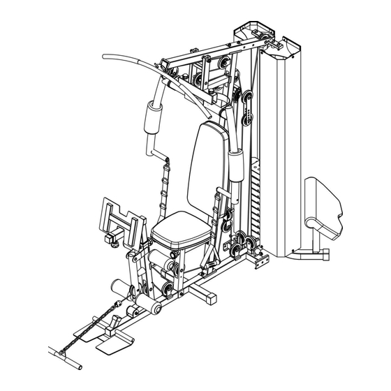
Performance Home Gym
Model: SCM-1160
Assembly and Use Instructions
Advertisement
Table of Contents

Related Manuals for SincMill SCM-1160


Summary of Contents for SincMill SCM-1160
- Page 1 NOTE: Please read all instructions carefully before using this product Contents Important Precautions Component - Parts Performance Home Gym Components - Fixings Model: SCM-1160 Assembly Operation and Adjustment Assembly and Use Instructions Maintenance Parts List Model SCM-1160 Retain This Manual for...
-
Page 2: Table Of Contents
Contents Before you Begin Safety Information Components-Parts Components-Fixings Pre-assembled parts Assembly Instructions 10-26 27-30 Exercise Information Parts List 31-32 Use Google Browser to scan the QR code below to view the product technical documentation page, including the latest version of Electronic Instruction, 3D assembly Video, Demo Video, etc. -
Page 3: Before You Begin
Before you Begin Thank you for selecting SCM-1160 Multi Purpose Home Gym. For your safety and benefit, please read this manual carefully before using the machine. As a manufacturer, we are committed to provide you complete customer satisfaction. If you have any questions, or find there are missing or damaged parts, we guarantee you complete satisfaction through direct assistance from our factory. -
Page 4: Safety Information
Safety information Important – Please read fully before assembly or use This exercise equipment is built for optimum safety. However, certain precautions apply whenever you operate a piece of exercise equipment. Be sure to read the entire manual before you assemble , operate or use this equipment. -
Page 5: Components-Parts
Components - Parts Please check you have all parts listed below Note: Some of the smaller components may be pre-fitted to larger components. Please check carefully before contacting us regarding any missing components. - Page 7 If there are missing or damaged parts in the new products purchased, you can contact the distributor or shopping store customer service, and we will send them to you free of charge. If you need extra or spare parts, you can use Google to scan the QR code below to learn more.
-
Page 8: Components-Fixings
Components - Fixings Please check you have all parts listed below Note: The quantities below are the correct amount to complete the assembly. In some cases more hardware may be supplied than are required. Some of the fixings are pre-fitted to the larger components. Please check carefully before contacting us regarding any missing fixings. -
Page 10: Pre-Assembled Parts
Pre-assembled parts. No installation is required. Make sure that no small parts are missing and start the installation process. -
Page 12: Assembly Instructions
Assembly Instructions Use Google Browser to scan the QR code below to view the product technical documentation page, including the latest version of Electronic Instruction, 3D assembly Video, Demo Video, etc. Paper manuals are not guaranteed to be up to date and there will be many installation details that cannot be added. - Page 13 Assembly Instructions Step 2 1. Attach the front vertical frame(3#) onto the base frame(1#). Carefully align the holes and secure them with 2 pc M10*70 carriage bolt(27#), 1 pc bracket(24#),2pcs Ø10 washers(44#) and 2pcs M10 Aircraft nuts(46#) . 2. Attach the seat pad support(6#) to the front vertical frame(3#) and secure them with 2pcs M10*70 Carriage bolt(27#),1pc bracket(24#),2pcs Ø10 washers(44#),2pcs M10 Aircraft nuts(46#) .
- Page 14 Assembly Instructions Note: #82 is a shock absorbing rubber pad. #100 has the large U-shaped groove facing down and the small U-shaped groove facing up. The side with the spherical groove should face up. Handle part #92 gently to avoid damaging the coating of #22.
- Page 15 Assembly Instructions The area where #27 screws are installed might be a little difficult to push #22 so please slightly loosen #3 screws (don't unscrew the nuts completely) to adjust their clearance distance, and finally tighten them together. Do not tighten #34 and #91 when connecting them, just connect them a little bit (10%) and lower #91the height as much as possible to make the...
- Page 16 Assembly Instructions Note: All movable joints and the pulley system behind require regular grease maintenance to improve the comfort and the average life of the machine. Do not tighten the nuts on both sides of #26 and #19 too much. Just let #15 and #19 turn flexibly.
- Page 17 Assembly Instructions Note: When tightening #83 enough, the backrest or seat cushion will stay stable and won’t wobble. When it’s in a loose status, it can be pulled and adjusted the position of the backrest or seat cushion. Tighten the #30 bolt moderately, so that #5 can rotate flexibly, and it will not shake too much.
- Page 18 Assembly Instructions Do not tighten #38 too much and let them to turn flexibly. Hold the bottom of #78, turn it left and right and push it upward to install it on the arm. Be careful not to block the hole on the handle. When the arm #7 and #8 are tilted at an angle, #113 is difficult to pull and adjust, so...
- Page 19 Assembly Instructions Note: Please make sure the direction of #10 is right. #84 is a rotary adjustment knob, which can be tightened to reduce the wobbling of #10. Step 8 Attach the 2pcs handle(4#) into the butterfly frame as the diagram shows. Secure them with 2pcs M10*25 Allen bolt(37#) and 2pcs Ø10 washer (44#).
- Page 20 Assembly Instructions Note: Embed the steel cables first, then install the pulleys one by one, and tighten the screws in the middle of the pulleys appropriately. Pulley needs to be flexible. Note: There is a steel post on the right side of pulley F. Please do not let the steel cable touch it. #94 and #95 cables are quick replacement cables if they worn out or were damaged due to misinstallation or derailment or prolonged use.
- Page 21 Step 9 A Feed the bolt end of the 3215mm Upper cable (94#) through opening in Upper frame . Place 1PC Pulley (79#) below the cable and secure the 1 pulley using 1PCM10 × 45 Allen bolt (35#) ,2PC Ø10 washers(44#)and 1XM10 Aircraft nut (46#).
- Page 22 Assembly Instructions !!! Note: If the direction of #19, the U- shaped bracket, is wrong, all cables will be shortened, just turn to the correct direction. #19 must point to #7 and #8 the butterfly arms.
- Page 23 Step 10 A. Attach the end of the 3020 MM butterfly cable(96#) to the hook and place 1X pulley (79#) below the cable , Secure the pulley to the swivel pulley bracket(19#) with 1X M10X45 Allen bolt (35#),2X Ø10 washer (44#) and 1pcM10 Aircraft nut (46#). B Draw the cable around the pulley and upwards, Install another pulley with the same way in above A .
- Page 24 Assembly Instructions Note: The hole position of #23 is optional. It can adjust the tightness of the rope of the pulley system. The cable should be adjusted to 97-100% tightness. There is a steel post below Pulley A,E and above Pulley B. Please do not let the steel cable touch them.
- Page 25 Step 11 Note: Embed the steel cables first, then install the pulleys one by one, and tighten the screws in the middle of the pulleys appropriately. If the skin of the steel cable is broken, it needs to be trimmed with scissors and sprayed with paint to avoid long-term dampness and rust.
- Page 26 Assembly Instructions The weight cover was folded into a square and placed in box #1. Because the height of #91 is low in step 4, it will be easier to install the weight cover. Finally, properly tighten #91 so that the weight cover is flat and unrolled, but do not over- tighten it to avoid...
- Page 27 Assembly Instructions The screws of these three pads are supposed to be screwed at 70% first, and then tightened 100% after all screws are installed into the holes. Step 13 Attach the seat pad (98#) onto the adjustment support and secure them with 4pcs M8*18 Allen bolt (39#) and 4pcs Ø8 washer(43#).
- Page 28 Assembly Instructions #52 should be installed at 70%. If #114 is affecting your foot stretch, you can simply remove it and install it when needed. Congratulations on completing all the installation! Please remember to regularly apply lubricant to the steel cables, weight block tracks and other parts which may produce friction.
-
Page 29: Exercise Information
Exercising Information Before starting to exercise How you begin your exercise programme depends on your physical condition. If you have been inactive for several years or are severely overweight, you must start slowly and increase a few minutes per workout. Initially, you may be able to exercise only for a few minutes in your target zone;... - Page 30 Exercising Information Muscle chart Aerobic Exercise Aerobic exercise improves the fitness of your lungs and heart - your body’s most important muscle. Aerobic exercise fitness is promoted by any activity that uses your large muscles (arms, legs or buttocks, for example). Your heart beats quickly and you breathe deeply.
- Page 31 Exercising Information Warming up and Cooling down exercises Each workout should include the following three parts: 1. A warm up, consisting of 5 to 10 minutes of stretching and light exercise. A proper warm up increases your body temperature, heart rate and circulation in preparation for exercise. 2.
- Page 32 Calf / Achilles stretch Exercising Information With one leg in front of the other, reach forward and place your hands against a wall. Keep your back leg straight and your back foot flat on the floor. Bend your front leg, lean forward and move your hips toward the wall.
-
Page 33: Parts List
Parts List Name Qty. No. Name Main Base Frame M10X28 Allen Bolt Rear Stabilizer M10X25 Allen Bolt Front Vertical Frame M10X16 Allen Bolt Handle M8X18 Allen Bolt Front Support Frame M8X40 Allen Bolt Sead Pad Support M6X20Allen Bolt Left Butterfly Frame φ6 Washer Right Butterfly Frame φ8 Washer... - Page 34 Name Name Rubber Bumper Backrest Pad Anti Slip Seat Pad Sticker Arm Curl Pad Long Rubber Bumper Weight Plate φ24.5Xφ31X460 Handle Grip Weight Stem φ24Xφ31X130 Handle Grip Weight Stack Cover φ22Xφ90X175 Form Roll Foam Roll Tube Butterfly Form Roll U shape Bracket 19 105 φ97 Pulley Leg Press Adjustment...
Need help?
Do you have a question about the SCM-1160 and is the answer not in the manual?
Questions and answers
The set comes with a bottle of silicone lubricant. The manual does not specify exactly where to apply the lubricant, how much to apply, and how frequently to apply. Thank you for your assistance
Silicone lubricant should be applied regularly to the steel cables, weight block tracks, and other parts that may produce friction. The exact amount is not specified, but it should be enough to reduce friction without over-applying. The frequency of application is described as "regularly," which typically means as needed based on use, or when friction or noise is noticed.
This answer is automatically generated
When installing pulleys D and E on step 9 the cable wants to pull off the tracks because they are not in line. I might be misunderstanding the instructions
To properly align pulleys D and E during installation of the SincMill SCM-1160 and prevent the cable from coming off the tracks:
1. Embed the steel cable first before installing the pulleys.
2. Align pulleys one by one and tighten the screws in the middle appropriately.
3. Make sure the cable does not touch the steel posts located below Pulley A and E, and above Pulley B.
4. Adjust the tightness of the cable to 97–100% using the optional hole positions on part #23.
This ensures correct alignment and prevents the cable from derailing.
This answer is automatically generated
Received two boxes.... one says 1of 4 and the other 2 of 4. Is there actually 4 boxes or two that completes this set
The exact number of boxes included in the SincMill SCM-1160 set is not specified in the provided context. However, it is mentioned that the products are large and heavy and were shipped in multiple boxes with different tracking numbers.
This answer is automatically generated