Table of Contents
Advertisement
Quick Links
Thank you for purchasing this Panasonic product.
■ This manual is common to all the models regardless of suffixes of the Model No.
z for India
WD: White model
z for Taiwan
BT: Black model
z for other countries or regions
B: Black model
■ Before operating this product, please read the instructions carefully and save this manual
for future use.
■ Before using this product, be sure to read "Read this first!" ( x pages 5 to 16).
Operating Instructions
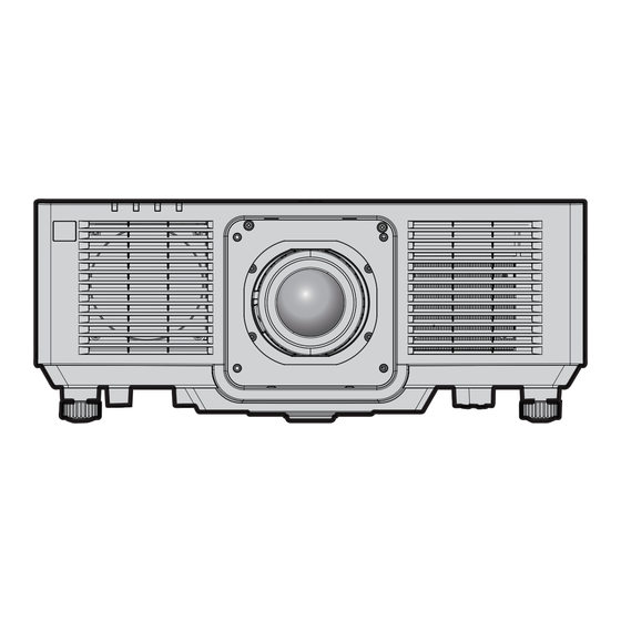
LCD Projector
Model No.
W: White model
Functional Manual
Commercial Use
PT-MZ882
PT-MZ782
PT-MZ682
ENGLISH
DPQP1564ZA/X1
Advertisement
Table of Contents


Need help?
Do you have a question about the PT-MZ882 and is the answer not in the manual?
Questions and answers
How do you replace the bulb?