Advertisement
Quick Links
KE2 Temp + Defrost
For Medium Temperature Applications with Air Defrost
Installation Manual
This reference should remain on site with the installed KE2 Temp + Defrost controller.
A
Select Mounting Location
The KE2 Temp is designed for a wide range of applications; therefore
there are many potential installation locations. Breaking down the in-
stallation location by application provides the most helpful reference.
Application
Locations
Undercounter
Evaporator cabinet
Outside controlled space
Walk-in
Evaporator cabinet
Adjacent to entrance
Side-by-side
Above door
© Copyright 2016 KE2 Therm Solutions, Inc., Washington, Missouri 63090
(pn 20611)
B
D
C
E
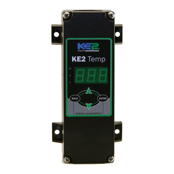
What's in the Kit - Parts List
The following parts are included in the
KE2 Temp + Defrost kit:
F
A
(1) KE2 Temp + Defrost controller
Programming
Press & hold ENTER button
B
(1) temperature sensor - 45"
to access setpoint menu
Use arrow buttons to
select function:
C
tS = Temperature Setpoint
(4) self-tapping mounting screws
diF =
CSH = Max Compressor
Starts/ Hour
D
(1) liquid tight cord grip
dPd = Defrost Per Day
dFt = Defrost Time
E
(1) sensor ziptie
LAO =
tAd = Temp Alarm Delay
Adr = Mod Bus Address
Unt = Units for temp display
F
(1) programming sticker
Press ENTER & use arrows
to change value
G
Press & hold ENTER button
(2) screws for high voltage shield
Alarms
When amber LED is lit:
Supplies List
SSA = Shorted Sensor Alarm
OSA = Open Sensor Alarm
HtA = High Temp Alarm
All of the accessories required for the controller to work
LtA = Low Temp Alarm
pn 20679
06/14
are supplied, however, standard truck stock items are re-
quired to install the controller. A list is provided below:
conduit to go between the controller & evaporator
(2) conduit connectors (straight or elbow as required)
(4) high voltage wires matched to the load of the
F
liquid line solenoid/compressor and the controller.
wire labeling (numbers, colors, etc.)
additional wire ties
18 gauge twisted shielded pair (if extending sensor
wires/adding communication)
foam insulation (if running wires outside the space)
silicone (for sealing any box penetrations)
Walk-in
Wine Cabinet
February 2016
Under Counter
Commercial
Q.1.20
Advertisement

Subscribe to Our Youtube Channel
Related Manuals for KE2 Temp + Defrost


Summary of Contents for KE2 Temp + Defrost
- Page 1 (pn 20611) For Medium Temperature Applications with Air Defrost Installation Manual This reference should remain on site with the installed KE2 Temp + Defrost controller. What’s in the Kit - Parts List The following parts are included in the KE2 Temp + Defrost kit:...
-
Page 2: Wiring The Controller
With the high voltage cover removed, the two screw terminal connectors can be seen. The 2-position connector is the controller’s power supply. The voltage selector switch should be positioned to match the voltage supplied. © Copyright 2016 KE2 Therm Solutions, Inc., Washington, Missouri 63090... - Page 3 (1) Relay Single Pole Double Throw Resistive Horsepower 1 hp 2 hp 1/4 hp 1/2 hp Pilot Duty 800VA 720VA 290VA 360VA Replace high voltage shield after wiring is completed. © Copyright 2016 KE2 Therm Solutions, Inc., Washington, Missouri 63090...
-
Page 4: Low Voltage Connections
Communication The KE2 Temp includes RS-485 Modbus commu- nication. RS-485 communication should be con- nected to the A, B, and Sh (shield) connections. © Copyright 2016 KE2 Therm Solutions, Inc., Washington, Missouri 63090... -
Page 5: Programming The Controller
Installation Manual Programming the Controller KE2 Temp + Air Defrost Basic Navigation Many applications of the KE2 Temp + Air Defrost can use the controller’s preset defrosts per day. This automatically spaces Understanding the KE2 Temp + Air Defrost’s menu structure the defrosts throughout the day, based on the number of de- will simplify configuration. -
Page 6: Advanced Setpoints
Units for temp display *Selecting fewer than 5 compressor starts per hour results in the starts per hour feature being turned off. The compressor will then function on temperature only. © Copyright 2016 KE2 Therm Solutions, Inc., Washington, Missouri 63090... - Page 7 (room temp will be displayed). HAO = High Alarm O set LAO = Low Alarm O set © Copyright 2016 KE2 Therm Solutions, Inc., Washington, Missouri 63090 tAd = Temp Alarm Delay Adr = Mod Bus Address...
-
Page 8: Dimensions - Inches
2.79 2.30 End View 2.14 © Copyright 2016 KE2 Therm Solutions, Inc., Washington, Missouri 63090 KE2 Therm Solutions Q.1.20 February 2016 supersedes bulletin Q.1.20 June 2015 and all prior publications. 12 Chamber Drive . Washington, MO 63090 1.888.337.3358 . www.ke2therm.com...
Need help?
Do you have a question about the Temp + Defrost and is the answer not in the manual?
Questions and answers