Table of Contents
Advertisement
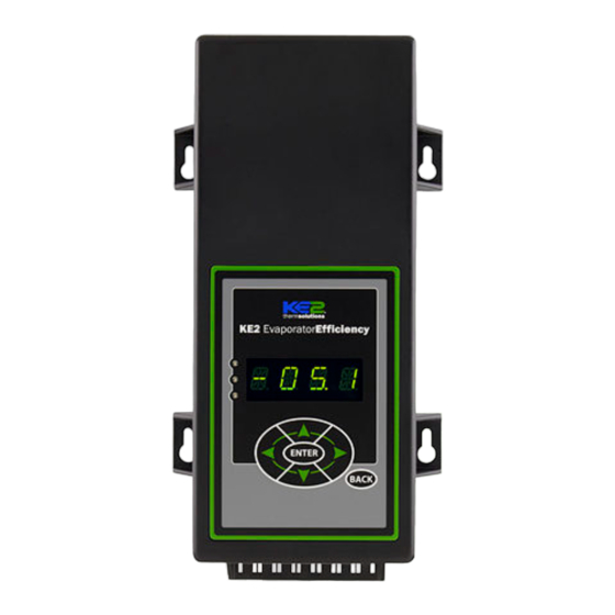
KE2 EvaporatorEfficiency
Quick Start Guide
This reference should remain on site with the installed KE2 Evaporator Efficiency controller.
L
Parts List
The following parts are included in the
KE2 Evaporator Efficiency (KE2 Evap) controller kits:
Kit #20178 with 120/208-240 VAC controller
Kit #20844
with 120/208-240 VAC controller
Kit #20631
with 120/208-240 VAC controller
Kit #21096
with 120/208-240 VAC controller
Kit #20222
Beacon® I & II replacement controller
A
(1) KE2 Evaporator Efficiency controller
B
(1) high voltage safety shield
C
(3) 10' temperature sensors
D
(4) 90 degree quick disconnects
(5) self-tapping screws
E
F
(2) course thread screws (1) fine thread machine screw with
lock washer
G
(1) KE2 Terminal Board
(1) KE2 Evap Navigation sticker
H
I
(2) 1/2" plastic knockout plugs
J
(4) wire ties (rated for low temp)
K
(1) Air sensor mount
L
(1) 5-position screw down terminal (for EEV)
(4) 3-position screw down terminals (for power in, transducer
M
and 3A relay)
(9) 2-position screw down terminals (for sensors and digital
N
input, analog output)
1) 120 Voltage jumper
O
(1) 208-240V Voltage jumper (already on back of KE2 Evap)
P
© Copyright 2015 KE2 Therm Solutions, Inc., Washington, Missouri 63090
A
B
D
K
M
C
E
F
G
I
J
N
Supplies List
The KE2 Evap is supplied with all of the accessories required for the con-
troller to work, however, standard truck stock items will also be required
to install the controller. To simplify the installation, a list of items has
been provided.
Conduit to go between the controller and the evaporator
(2) Conduit connectors (straight or elbow as required)
(11) High voltage wires matched to the load of the heaters, fans,
liquid line solenoid, alarm (if used), and the controller.
(8) Spade Connectors matched to gauge of high voltage wires
Wire labeling (numbers, colors, etc.)
Additional wire ties
18 gauge twisted shielded pair (if extending sensor wires)
Foam insulation if running wires outside the space.
Silicone (for sealing any box penetrations)
Accessories to Aid in Installation
The following parts are available separately:
10' Wire Harness pn 20736,
25' Wire Harness pn 20670
40' Wire Harness pn 20737
KE2 Evap Mounting Box pn 20687
Further information on the Wire Harness and Mounting Box can be found in
literature Q-1-21.
20844 KE2 Ultimate Install kit includes KE2 Mounting Box pn 20687 and 40'
colored temperature sensors
20631 kit does not include temperature sensors
21096 KE2 Supermarket Retrofit kit also includes KE2 Mounting Box pn 20687,
10' Wire Harness pn 20736, Ethernet Adaptor pn 20938, & Door Switch 20543
20222 Beacon® kit includes an extra temperature sensor, and pressure
transducer with cable.
July 2015
Controller Navigation
pn 21061 9-14
Lights:
Red - critical alarm (system not running)
Yellow - non-critical alarm (system running)
Green - compressor should be on
H
- compressor waiting on timer to start/stop
Moving through controller menus:
Left Arrow & Right Arrow
Use to move between Menus columns
ENTER
Up Arrow & Down Arrow
Scroll through Menu Parameters
BACK
Return to Main Menu:
BACK
Press BACK to return to the previous view.
Toggle beween
ENTER
Press ENTER to go from parameter to value.
description & value :
Press and hold ENTER for 3 seconds, when
Change settings:
ENTER
ENTER
display is blinking changes can be made.
Save changes:
ENTER
Press and hold ENTER for 3 seconds.
If you lose your place:
BACK
Press BACK 3 - 4 times
Menu Layout:
Enter
Variables
Alarms
Setpoints
Manual*
Password
(view only)
(view only)
ROOM TEMP
NO ALARM
ROOM TEMP
MANUAL CONTROL
FIRMWARE VERSION
EMAIL FAILURE
DERIVATIVE
CLEAR MD
* For manual defrost use MANUAL CONTROL
24-hour Emergency Support: 1.888.337.3358
www.ke2therm.com
O
P
Q.1.3
Advertisement
Table of Contents

Related Manuals for KE2 Efficiency


Summary of Contents for KE2 Efficiency
- Page 1 Q.1.3 July 2015 KE2 EvaporatorEfficiency Quick Start Guide This reference should remain on site with the installed KE2 Evaporator Efficiency controller. Controller Navigation pn 21061 9-14 Lights: Red - critical alarm (system not running) Yellow - non-critical alarm (system running)
-
Page 2: Trouble Shooting Diagram
Some may even say “frost is our friend. ” It is not un- heat and subcooling. common to see a small amount of frost on the coils that have KE2 Evaporator Efficiency (KE2 Evap) controllers installed. The KE2 Evap... - Page 3 Enough wire should be left to move the sensor to the opposite end of the evaporator. Make note of the locations you have determined for placement of the coil sensors. © Copyright 2015 KE2 Therm Solutions, Inc., Washington, Missouri 63090...
- Page 4 The wire should be long enough to account for the necessary con- nections in the controller and evaporator. Use the optional KE2 Wire Harness, or select different colored wires, (blue - fan, orange - heaters, yellow - solenoid, purple - alarm). This will simplify the installation and troubleshooting.
-
Page 5: Wiring The Controller
Plug the black with orange stripe to the COM terminal. Plug the orange w. black stripe to the NO position of Defrost Relay. Confirm combined heater load is not over 20 amps. © Copyright 2015 KE2 Therm Solutions, Inc., Washington, Missouri 63090... - Page 6 Verify power is no longer present using a multimeter. Evaporator wiring Now that the conduit is prepared, it can be connected to the evaporator. Locate the proper sized knockout and carefully remove knockout. Connect conduit to the evaporator © Copyright 2015 KE2 Therm Solutions, Inc., Washington, Missouri 63090...
- Page 7 Attach the wire connected to the NO terminal on the Fan Relay to one of the fan leads. Connect L2/Neutral to remaining fan lead. © Copyright 2015 KE2 Therm Solutions, Inc., Washington, Missouri 63090...
- Page 8 Attach the wire from the COM on the L.L. Solenoid/Compressor relay to the L1/Line Voltage. Connect L2/Neutral to the remain- ing L.L. Solenoid/Compressor lead. © Copyright 2015 KE2 Therm Solutions, Inc., Washington, Missouri 63090...
- Page 9 Q.1.3 July 2015 Page 9 KE2 EvaporatorEfficiency Quick Start Guide Wiring Schematic - Controller New Installation © Copyright 2015 KE2 Therm Solutions, Inc., Washington, Missouri 63090...
- Page 10 Q.1.3 July 2015 Page 10 KE2 EvaporatorEfficiency Quick Start Guide Wiring Schematic - Controller with KE2 Contactor Box © Copyright 2015 KE2 Therm Solutions, Inc., Washington, Missouri 63090...
- Page 11 In these instances, the method shown in Figure 26 can be used. © Copyright 2015 KE2 Therm Solutions, Inc., Washington, Missouri 63090...
-
Page 12: Strain Relief
Place the controller on the mounting screws and tighten down the screws. Final Step Leave the installation instructions onsite in a convenient location, where it can be easily located, for future service. © Copyright 2015 KE2 Therm Solutions, Inc., Washington, Missouri 63090... -
Page 13: Specifications
Pressure Transducer Part Number black 20222 Beacon brown Wiring Detail Beacon® II green replacement white controller green black required. signal Pressure Transducer ground Temperature Sensors (4) blue Beacon® II white black © Copyright 2015 KE2 Therm Solutions, Inc., Washington, Missouri 63090... - Page 14 6 The Setpoint parameters shown TEMP UNITS in BOLD ITALIC are used for AIR TEMP DIFF bonded controllers only. EXTREME TEMP DIFF PROPORTIONAL 7 Only displayed when Run Time INTEGRAL Defrost is selected. DERIVATIVE © Copyright 2015 KE2 Therm Solutions, Inc., Washington, Missouri 63090...
-
Page 15: User Interface
Mode consists of as little as 3 setpoints that must be config- Smart Access Motor Type (Unipolar/Bipolar) ured for KE2 Evap to begin controlling the system. See Table 2. Motor Step Rate Max Valve Steps The first setpoint the user is asked to enter is the desired ROOM TEMP. - Page 16 Introduction to Smart Access Smart Access doesn’t require port forwarding or establishing a vpn. All the KE2 Evap needs is a physical connection to the net- Smart Access provides quick and easy, real time access to your refrig- work router with a cat 5 cable. Smart Access will automatically eration systems 24/7 connect to your personal web portal.
- Page 17 For additional information on SmartAccess, visit IP-10.10.52.19 IP-10.10.52.19 http://ke2therm.com/productliteratureevap4. html, and see bulletins A.1.76 The KE2 Evap v4.0 00:04:A3:14:E5:92 00:04:A3:14:E5:92 with Smart Access and Q.1.34 Smart Access Setup and Customizing. © Copyright 2015 KE2 Therm Solutions, Inc., Washington, Missouri 63090...
- Page 18 A coefficient to the valve control algorithm that increases valve responsiveness INTEGRAL A coefficient to the valve control algorithm that increases valve responsiveness DERIVATIVE Should not be adjusted unless instructed by KE2 Therm technical support © Copyright 2015 KE2 Therm Solutions, Inc., Washington, Missouri 63090...
- Page 19 -10°F ELEC, AIR, HOT GAS COMP ON, HOT GAS COMP OFF ELEC MECHANICAL, KE2 RSV, KE2 HSV, SER/SEI 1 TO 20, SER B TO L, SEI 30, SEI 50, SEH, ETS12 TO 50, MECHANICAL ETS100, ETS250/400, CAREL, CUSTOM; BIPOLAR, UNIPOLAR...
-
Page 20: Manual Menu
ONLY FOR SITEVIEW MANAGER: No communication to the SNTP server defined in Settings/Siteview Options KE2 Therm Solutions 209 Lange Dr. . Washington, MO 63090 © Copyright 2015 KE2 Therm Solutions, Inc., Washington, Missouri 63090 1.888.337.3358 . www.ke2therm.com Q.1.3 July 2015 supersedes Q.1.3 March 2015 and all prior publications.
Need help?
Do you have a question about the Efficiency and is the answer not in the manual?
Questions and answers