Advertisement
Quick Links
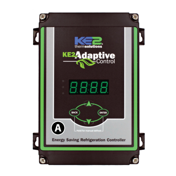
KE2 AdaptiveControl
Quick Start Guide
This reference should remain on site with the installed KE2 Adaptive Control controller.
A
D
H
Parts List
The following parts are included in the KE2 Adaptive Control
controller kits:
Kit # 21177 with 120/208-240 VAC controller
(1) KE2 Adaptive Control controller
A
B
(1) high voltage safety shield
C
(1) 3-pack of colored 15' temperature sensors
D
(6) 90° spade connectors
E
(2) straight spade connectors
F
(5) self-tapping screws
G
(2) 1/2" plastic knockout plug
H
(1) air sensor mount
I
(3) course thread screws
J
(1) KE2 Terminal Board*
(1) Warranty card
(not shown)
© Copyright 2016 KE2 Therm Solutions, Inc., Washington, Missouri 63090
E
F
(pn 21177)
B
I
G
Supplies List
The KE2 Adaptive Control is supplied with all of the accessories re-
quired for the controller to work, however, standard truck stock items
will also be required to install the controller. To simplify the installa-
tion, a list of items has been provided.
Conduit to go between the controller and the evaporator
(2) Conduit connectors (straight or elbow as required)
(8) High voltage wires matched to the load of the heaters,
fans, liquid line solenoid, and the controller.
(8) Spade Connectors matched to the gauge of high volt-
age wires
Wire labeling (numbers, colors, etc.)
Wire ties
18 gauge twisted shielded pair (if extending sensor wires)
Foam insulation if running wires outside the space.
Silicone (for sealing any box penetrations)
Accessories to Aid in Installation
The following parts are available separately:
10' Wire Harness pn 20736, 25' Wire Harness pn 20670, or 40' Wire
Harness pn 20737
Further information on the Wire Harness can be found in literature
Q.1.21.
* When used with the KE2 Adaptive Control controller, the fuses must be sized to
match the application (i.e. Replace existing fuses with 30 Amp Time Delay fuses
for fans and compressor)
Q.1.35
January 2016
C
J
Advertisement

Related Manuals for KE2 AdaptiveControl


Summary of Contents for KE2 AdaptiveControl
- Page 1 Further information on the Wire Harness can be found in literature Q.1.21. * When used with the KE2 Adaptive Control controller, the fuses must be sized to match the application (i.e. Replace existing fuses with 30 Amp Time Delay fuses for fans and compressor) ©...
-
Page 2: Trouble Shooting Diagram
When the ef- ing systems. Typically the superheat on a TEV is set when there is not ficiency of the coil is reduced due to excessive frost, the KE2 Adaptive product in the controlled space, if it is set at all. - Page 3 Typically last spots to defrost Steps to Ensure Proper Coil Sensor Location KE2 Therm recommends locating the coil sensor as described above. Typically the coldest spot is on the side of the suction header/expan- sion valve side of the evaporator. Select two places that are the last to defrost, preferably at each end of the evaporator.
- Page 4 The wire should be long enough to account for the necessary con- nections in the controller and evaporator. Use the optional KE2 Wire Harness, or select different colored wires, (blue - fan, orange - heaters, yellow - solenoid, purple - alarm). This will simplify the installation and troubleshooting.
- Page 5 Controller Power Strip the end of the wires used to provide power to the controller (If using the KE2 Wire Harness the wires are pre-stripped) Crimp on female spade connectors (Item E from list on page 1) Plug into the board as indicated in Wiring Schematic.
- Page 6 Plug the black with a blue stripe to the COM terminal. Plug the blue with a black stripe to the NO position of the Fan Relay Confirm combined fan motor load is not over 30 FLA. © Copyright 2016 KE2 Therm Solutions, Inc., Washington, Missouri 63090...
- Page 7 Verify power is no longer present using a multimeter. Evaporator wiring Now that the conduit is prepared, it can be connected to the evaporator. Locate the proper sized knockout and carefully remove knockout. Connect conduit to the evaporator © Copyright 2016 KE2 Therm Solutions, Inc., Washington, Missouri 63090...
- Page 8 Fan Relay to one set of the fan leads. This wire will be connected to the NO of the fan relay on the controller. Connect L2/Neutral to remaining fan leads. © Copyright 2016 KE2 Therm Solutions, Inc., Washington, Missouri 63090...
- Page 9 Attach the yellow wire with black stripe connects to the NO terminal on the L.L. Solenoid/ Compressor relay to a solenoid lead Connect L2/Neutral to the remain- ing L.L. Solenoid/Compressor lead. © Copyright 2016 KE2 Therm Solutions, Inc., Washington, Missouri 63090...
- Page 10 Q.1.35 January 2016 Page 10 KE2 AdaptiveControl Quick Start Guide Figure 8 - Wiring Schematic - Ladder Diagram Figure 8 - Wiring Schematic - Using KE2 Terminal Board © Copyright 2016 KE2 Therm Solutions, Inc., Washington, Missouri 63090...
- Page 11 Do not allow the metal portion of the air sensor to touch any- thing other than air. It should not touch the bracket, nylon cable tie, or any other solid surface. © Copyright 2016 KE2 Therm Solutions, Inc., Washington, Missouri 63090...
- Page 12 Laboratories as above 30V. The higher voltage the more likely it is to introduce interference, and the more important to avoid. If crossing a high voltage line is necessary, the sensor wiring should be run at right angles to prevent noise. © Copyright 2016 KE2 Therm Solutions, Inc., Washington, Missouri 63090...
- Page 13 KE2 AdaptiveControl Quick Start Guide Setting the dip switch to activate on board buzzer To disable the audible alarm buzzer feature of the KE2 Adaptive Control the dip switch must be switched to OFF (default from the factory is ON) The red dip switch is located at the bottom of the controller, and is equipped with a switch that indicates ON or OFF.
- Page 14 HEtr SySt SySt EdiF CPrl CPrl dtSP dtSP dtSP dFrl dFrl drnt drnt drnt Fnrl Fnrl fdSP fdSP fdSP ALSt ALSt Fndt Fndt Fndt FndF FndF FndF CLAL CLAL CLAL © Copyright 2016 KE2 Therm Solutions, Inc., Washington, Missouri 63090...
-
Page 15: Specifications
Changing Setpoints User Interface When the parameter value is displayed it may be changed by using The KE2 Adaptive Control’s onboard user interface uses the familiar the Up, Down, and ENTER buttons. 4- button arrangement to simplify navigation through the control- ler’s menus. - Page 16 Table 3 - Controller Menus and Menu Parameters Alarms Non Adjustable (view only) When the KE2 Adaptive Control is in alarm, it notifies the user by illuminating the amber LED, and displaying the appropriate Alarm Code: Alarm Alarm Name Description...
- Page 17 Temp Alarm Delay 1 min 60 min 180 min Modbus address Temp units FAH or CEL CLAL CLAL CLAL Not a setpoint, press “Enter” and hold until display changes. All Alarms Cleared © Copyright 2016 KE2 Therm Solutions, Inc., Washington, Missouri 63090...
-
Page 18: Variables Menu
In variables menu, display when 1st or 2nd Auxiliary input (AU1 or AU2) set to dFin (Defrost Interlock) and is inactive Disabled Setpoint Choice for input type for 1st or 2nd Auxiliary input (AU1 or AU2)- input is not in use © Copyright 2016 KE2 Therm Solutions, Inc., Washington, Missouri 63090... - Page 19 Defrost Per Day Setpoint Number of defrosts per day 0-12, Custom (CUS) dPTR Defrost parameter Setpoint If Defrost Initiation mode (dFit) = Demand Defrost (dEnd); Coefficient to KE2 Defrost algorithm drAn Drain System State Displays when system is in drain mode drCL...
- Page 20 CUS is displayed. play Defrost 1 (d1). KE2 Therm Solutions © Copyright 2016 KE2 Therm Solutions, Inc., Washington, Missouri 63090 Q.1.35 January 2016 supersedes Q.1.35 October 2015and all prior publications, 12 Chamber Drive . Washington, MO 63090 636.266.0140 . www.ke2therm.com...
Need help?
Do you have a question about the AdaptiveControl and is the answer not in the manual?
Questions and answers