
Related Manuals for Schaeffler EWELLIX e-MOVEKIT


Summary of Contents for Schaeffler EWELLIX e-MOVEKIT
- Page 1 CATEGORY INSTALLATION, OPERATION AND MAX 2 LINES MAINTENANCE MANUAL Heading_cover e-MOVEKIT max 2 lines Subheading max 2 lines Feature 1 max 2 lines Feature 2 max 2 lines Feature 3 Feature 4...
-
Page 2: Table Of Contents
e-MOVEKIT Contents 1. General information ............3 6.4.2 Operation with Analog Throttle input ...... 19 6.5 Operation of System Integration e-MOVEKIT with CAN 1.1 Information in this manual ..........3 1.2 Explanation of symbols and signal words.....3 commands ..............20 1.3 e-MOVEKIT designation ..........4 6.5.1 Operation with CAN throttle commands ....21 6.5.2 Transmit PDO 1 ............22 1.4 Related documents ............4 1.5 Target audience .............4... -
Page 3: General Information
e-MOVEKIT 1. General information DANGER 1.1 Information in this manual Indicates a dangerous situation, which will lead to death or serious personal injury, if the precautionary measures are This manual provides important information on how to work ignored. with the actuator (also called device or drive) safely and efficiently. -
Page 4: E-Movekit Designation
e-MOVEKIT 1.3 e-MOVEKIT designation The e-MOVEKIT contains of a controller and additional ca- bles to connect to the motor. The motor needs to be ordered together with the complete actuator separately using the CASM-100 type key. Ordering key C A M - C - 0 0 0 Type Quick start e-MOVEKIT (including cables, sensors) -
Page 5: Safety
e-MOVEKIT 2. Safety 2.2 Functional safety This section provides safety aspects supplementary to the safety aspects described in the relevant operating manuals of the included devices. Failure to comply with the guide- The e-MOVEKIT and its components Quick Start lines and safety instructions contained in this manual may e-MOVEKIT or System Integration e-MOVEKIT and CASM- result in serious hazards that could cause possible serious 100 actuator, are not functional safety systems compliant... -
Page 6: Potential Risks
e-MOVEKIT • The emergency-stop system must always be freely acces- sible. • To integrate e-MOVEKIT into a functional safety system with a STO (Safe Torque Off) safe condition, an external safety relay must be connected to the e-MOVEKIT control- ler power supply, triggered by a functional safety function. This functionality is already integrated into the Quick Start e-MOVEKIT. -
Page 7: E-Movekit Components
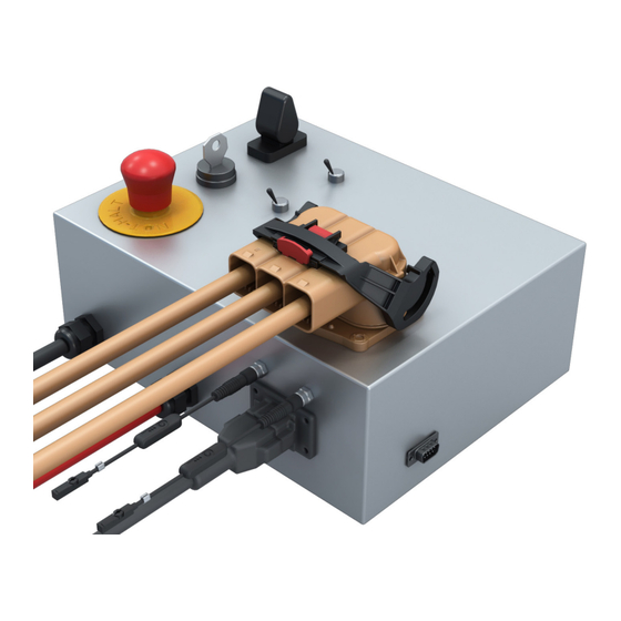
e-MOVEKIT 3. e-MOVEKIT components 3.1 Scope of delivery Quick Start e-MOVEKIT System Integration e-MOVEKIT 1. Quick Start e-MOVEKIT control box 1. System Integration e-MOVEKIT motor controller (Curtis AC F2-A-24-200-051) 2. Motor Power Cable (pre-installed on actuator) Not included, but necessary for operation 3. -
Page 8: System Requirements
e-MOVEKIT 3.2 System requirements Figure 2 • Battery power input 24V DC (max. 32V DC, min. 12V DC) at max. 200 A. • The battery needs to be configured in a way that allows for a current flow from the controller to the battery (battery charging by the controller is necessary for regenerative braking of the motor and increases the operation time of the battery). -
Page 9: Mechanical Installation
e-MOVEKIT 4. Mechanical installation For the installation of the CASM-100 actuator follow the installa- tion instructions from the actuator operating, installation and maintenance manual. For the installation of the System Integration e-MOVEKIT follow the installation instruction from the controller operating, installa- (VP-10005-EN-April 2023 tion and maintenance manual... -
Page 10: Electrical Installation
e-MOVEKIT 5. Electrical installation 5.1 Installation of Quick 4. Connect the AMPHENOL plug (Ref. 2 to Sec.3.1) of the Start e-MOVEKIT Motor Power Cable (pre-installed on the motor) to the corresponding receptacle (Ref. 1 to Sec.3.1) on the Quick Start e-MOVEKIT box. Make sure the connector is firmly 5.1.1 Tools required plugged in and the locking handle is closed. - Page 11 e-MOVEKIT Figure 4 Schematics Quick Start e-MOVEKIT 24VDC AMPSEAL J1-15 AMPSEAL J1-1 AMPSEAL J1-2 24V DC AMP M8 sensor input retracted AMPSEAL J1-5 24V DC pull-down (RND 205-01130) KEYSWITCH (IDEC YW1K-21BE10) MAIN AMPSEAL J1-4 AMPSEAL J1-14 24V DC pull-down AMPSEAL J1-12 AMPSEAL J1-9 AMPSEAL J1-23 AMPSEAL J1-12...
-
Page 12: Installation Of System Integration E-Movekit
e-MOVEKIT 5.2 Installation of System 1. Open the cover of the motor connection box Integration e-MOVEKIT 2. Connect the 3 motor phase terminals (U, V, W) to the motor power cables (to be ordered separately). The ca- For the installation of the System Integration e-MOVEKIT, bles need to be secured using the delivered washers and follow the instructions in the manufacturer operation manual nuts. - Page 13 e-MOVEKIT The AMPSEAL Connector Components & Part Numbers Table 2 Matching AMPSEAL 23-pin Component* Part Number 77068 0-1 AMPSEAL receptacle housing (the black vehicle- harness plug) 770520-3 Plug’s gold-plated socket terminals (strip form p/n) 770854-3 Plug’s gold plated socket terminals (loose piece p/n) Silo seal plug (for non-used pin positions with a 770678 -1)
-
Page 14: N11 Motor Interface
e-MOVEKIT Figure 11 AMPSEAL 23pin connector wiring Coil not used MAIN not used EM Brake not used Interlock Switch Return Sensor Sensor Motor Throttle Extended Extended not used I/O GND CAN HI Temp. (Slow down) (Stop) Sensor Sensor 5V DC ENC A ENC B not used... -
Page 15: Operation Of E-Movekit
e-MOVEKIT 6. Operation of e-MOVEKIT 6.1.2 Operation with Joystick Both the Quick Start e-MOVEKIT and System Integration e-MOVEKIT can be operated via an analogue voltage throttle signal or a throttle command via CANopen. Depending on CAUTION the operation mode, a different start-up sequence needs to Make sure that there is no person or object in the near vicinity be followed. -
Page 16: Operation Of Quick Start E-Movekit With Can Commands
e-MOVEKIT CAUTION NOTICE The limit switches are pre-configured to the actuator. Changing The Interlock Switch will send a command to the controller to close their position on the linear actuator will result in a loss of their the main contactor. Only when the main contactor was successfully functionality. - Page 17 e-MOVEKIT Table 5 For easy reference the following table can be used. Little endian is used. Throttle CMD Byte 0 Byte 1 Actuator movement 0x8000 Retracting v = 100% -100 % Retracting v = 80% -80 % 0x999A 0xB333 Retracting v = 60% -60 % 0xCCCD Retracting v = 40%...
-
Page 18: Change Max. Motor Speed Of Quick Start E-Movekit
e-MOVEKIT 6.3 Change Max. CAUTION ELECTROMECHANICAL BRAKE (N11 Motor Option) – The max. Motor Speed of Quick allowed motor speed for the electromechanical brake mounted Start e-MOVEKIT to the back of the N11 motor is at 3000rpm. Driving the motor at speeds higher than this will result in permanent damage and is prohibited. -
Page 19: Operation Of System Integration E-Movekit With Analog Throttle Input
e-MOVEKIT NOTICE 1. Power on the Quick Start e-MOVEKIT by turning the key MAIN CONTACTOR – The main contactor needs to be a coil- switch ON. based contactor. Any other type of main contactor will not work with the controller. Ewellix recommends the CURTIS/ALBRIGHT 2. -
Page 20: Operation Of System Integration E-Movekit With Can Commands
e-MOVEKIT Limit Switch Option In case the System Integration e-MOVEKIT is ordered with the Limit Switch Option enabled (Other Options – Sensors = 1), the limit switches need to be connected according to the wiring diagram shown in section 5.2.2 Fig.10 and table 10. CAUTION The limit switches need to be configured in a way that the actuator and the application where the actuator is built in cannot... -
Page 21: Operation With Can Throttle Commands
e-MOVEKIT 6.5.1 Operation with CAN throttle commands NOTICE NOTICE Changing the throttle mode while the box is in operation will The Interlock Switch will send a command to the controller to result in an error and will immediately stop the movement of the close the main contactor. -
Page 22: Transmit Pdo 1
e-MOVEKIT Figure 16 Controller State diagram Initialization Pre-Operational Stopped Operational 6.6 Transmit Mailbox Messages After the controller is switched to operational (see section 6.4.1 or 6.5.1) it will send cyclic messages about the most critical information of the controller and motor. General: All information will be sent as little endian. - Page 23 e-MOVEKIT Table 16 CAN identifier Byte 0 Byte 1 Byte 2 Byte 3 Byte 4 Byte 5 Byte 6 Byte 7 Capacitor Battery Controller Main 2A6h Volt Current Temperature State Capacitor Volt: Information: Battery voltage level at B+ of the controller Data Type: UNSIGNED 16 Unit:...
-
Page 24: Manual Release On Em-Brake
e-MOVEKIT 6.7 Manual Release on EM-Brake WARNING COLLAPS – Do not open the manual release or the electromagnetic brake (EM-brake) of the motor when the actuator is under load. This could lead to a collapse of the system. Opening the EM-brake while the actuator is under load should only be performed when a centrifugal brake is mounted to the gearbox. -
Page 25: Troubleshooting
e-MOVEKIT 8. Troubleshooting Table 18 Malfunction Possible cause What to do The actuator does not Control unit not operational Check battery power to controller/box move Check connections to motor Actuator is at an extreme position that does not allow further retraction or extension. - Page 26 ewellix.com © Ewellix All contents of this publication are the property of Ewellix, and may not be reproduced or given to third parties (even extracts) without permission. Although great care has been taken in the production of this catalog, Ewellix does not take any responsibility for damage or other loss resulting from omissions or typographical errors.
Need help?
Do you have a question about the EWELLIX e-MOVEKIT and is the answer not in the manual?
Questions and answers