Table of Contents
Advertisement
Quick Links
Advertisement
Table of Contents

Related Manuals for Schaeffler EWELLIX CAMT20


Summary of Contents for Schaeffler EWELLIX CAMT20
- Page 1 C ATEG O R Y MA X 2 L I N ES CAMT20 Linear actuator...
-
Page 3: Table Of Contents
Contents 1.0 General information ............4 6.0 Installation and first operation .........28 1.1 Information in this manual ..........4 6.1 Safety ................28 1.2 Explanation of symbols and signal words ......4 6.2 Installation location ............28 1.3 Limitation of liability ............5 6.3 Inspections before initial operation ......28 1.4 Copyright .................5 6.4 Installation ..............29 1.5 Spare parts ..............5... -
Page 4: General Information
C A M T 2 0 1.0 General information 1.1 Information in this manual This manual provides important information on how to work with the actuator (also called the device) safely and effi- DANGER ciently. The manual is part of the device, must always be Indicates a dangerous situation, which kept and should be available for personnel to read at all may lead to death or serious personal times. -
Page 5: Limitation Of Liability
1 .0 G e n e r a l i nfo r m a ti o n 1.3 Limitation of liability 1.5 Spare parts All information and notes in this manual were compiled tak- This actuator is not designed to be repaired. All warranty ing into consideration current standards and regulations, and service claims become null and void without notice if present status of technology and years of knowledge and... -
Page 6: Safety
C A M T 2 0 2.0 Safety Product lifetime This section provides an overview of important safety as- pects of installing, operating and maintaining this device. The CAMT linear actuator is designed for a service life of 10 Disregarding this Manual and safety regulations specified years in a typical medical procedure equipment application. -
Page 7: Responsibility Of The Owner And Processor
2 .0 S afe t y 2.2 Responsibility of the 2.3.1 Qualifications The following qualifications are specified for different areas owner and processor of activity listed in this manual: The device is designed for commercial applications by its • An instructed person (operator) owner or processor. The processor is the contracting part- Instructed by the customer in an orientation session on the ner of the reseller or the manufacturer. -
Page 8: Safety Equipment
C A M T 2 0 Integration of a safety mechanism to prevent WARNING Injury due to cracks and related openings in the housing of unintended triggering of the operating device the actuator and/or its accessories. (for certain applications) If the housing is damaged due to shock, breakage or heavy wear, cease using the device and follow the dismantling instructions. -
Page 9: Modifications Of Device
2 .0 S afe t y 2.7 Modifications of Essential performance The essential performance about the CAMT is to keep, hold device and move weights and loads. The risk management (Document L5671,0031) identifies the function regarding the safety of these linear actuators. All WARNING features or functions are performed properly. Unacceptable To avoid hazardous situations and to ensure optimal risks for patients, operators or others are performed and as- performance, do not make changes or modifications to the ... - Page 10 C A M T 2 0 Connection cable (CAMT <-> Control unit SCU; SCU <-> Operating elements) Description Plug Drawing-No Type Length Connecting cable straight: 2 x AWG16 & DIN 8p – Molex 6p 777400-1000 CAMT – SCU 4 x AWG24 Connecting cable straight: DIN 8p –...
- Page 11 2 .0 S afe t y Compliance for each Emission and Immunity standards The CAMT linear actuator (CAMT & SCU) is intended for use in the electromagnetic environment specified. It complies with the standard for emission class and group and immu- nity test level as follows. a) CAMT stand-alone CISPR 14-1 The CAMT is intended for use in the electromagnetic environment specified below. The customer or the user of the CAMT should assure ...
- Page 12 C A M T 2 0 b) CAMT and SCU CISPR 14-1 The CAMT is intended for use in the electromagnetic environment specified below. The customer or the user of the CAMT should assure that it is used in such an environment. Emissions test Compliance Electromagnetic environment - guidance RF emissions Complies The CAMT is not suitable for interconnection with other CISPR 14-1 equipment.
- Page 13 2 .0 S afe t y c) CAMT stand-alone / CAMT and SCU Electromagnetic immunity environment tested Portable and mobile RF communications equipment should be used no closer to any part of the CAMT, including cables, than the recommended separation distance calculated from the equation applicable to the frequency of the transmitter. These guidelines may not apply in all situations. Electromagnetic propagation is affected by absorption and reflection from structures, ...
- Page 14 C A M T 2 0 Recommended separation distances between portable and mobile RF communications equipment and the CAMT The CAMT is intended for use in the electromagnetic environment in which radiated RF disturbances are controlled. The customer or the user of the CAMT can help prevent electromagnetic interference by maintaining a mininum distance between portable and mobile RF communications equipment (transmitters) and the CAMT as recommended below, according to the maximum output power of the communication equipment.
-
Page 15: Technical Data
3 .0 Te c h n i c a l d a t a 3.0 Technical data 3.1 Ambient conditions • Indoor use only • Ambient temperature +10 to +40 °C • Atmospheric humidity from 5% to 85% • Air pressure from 700 to 1 060 hPa 3.2 Product label Type label (without options) 9. -
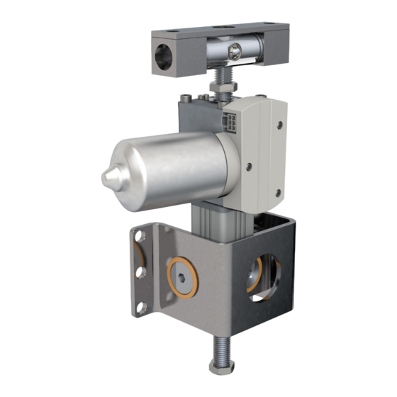
Page 16: Structure And Function
C A M T 2 0 4.0 Structure and function 4.1 Overview 1. Adjustable front and rear end stop 4.3 Structure and 2. Connection port (Molex Mini-Fit Jr. 6 Pole) 3. Gearbox function 4. Limit switches with cover 5. DC Motor Connection port 6. - Page 17 4 .0 S tr u c t u r e a n d f u n c ti o n tailed control and connection details please refer to chapter WARNING 4.5 Requirements for third party control units (manda- Safety hazard caused by interference tory in medical applications) (⮑ page 23) and chapter 4.6 When using a short protection tube in combination with a long Connections (⮑ page 23).
- Page 18 C A M T 2 0 Ultimately, in case of overload the control limits the current The upper and lower end position may be adjusted by changing the position of the end stops using standard tools: to prevent the motor from overheating and damaging the actuator.
-
Page 19: Attachment Options
4 .0 S tr u c t u r e a n d f u n c ti o n 4.4 Attachment options Fig. 6 Several types of attachments provide flexibility to install the CAMT on the supporting structure. Most feature a set of matching front and rear interfaces: • ... - Page 20 C A M T 2 0 It should be noted that to keep a low play configuration, the clevis pins used both for the front and rear attachments NOTE should be of matching dimension/tolerance. If the bore is to be used as the pivot point, it is recommended to Fig. 11 use a DIN 6325 cylinder pin with Ø...
- Page 21 4 .0 S tr u c t u r e a n d f u n c ti o n WARNING 4.4.4 Degrees-of-freedom (2-DOF) Safety hazard caused by wrong attachment The front bracket is designed and tested to be working with the brackets load in an axial direction.
- Page 22 C A M T 2 0 The 2 DOF rear brackets have the same 2 axes of rotation as 4.4.5 U-Bracket the front one (⮑ fig. 15). It is also possible to get a variant of the 1 DOF rear attach- It also comes fully assembled, adjusted to reduce the play to ment, the U-bracket (⮑ fig. 16).
-
Page 23: Requirements For Third Party Control Units (Mandatory In Medical Applications)
4 .0 S tr u c t u r e a n d f u n c ti o n 4.5 Requirements for For the 2-Hall encoder impulse transmitter, the third party control unit must fulfil the following additional requirements: third party control units • Feed the hall sensors with a voltage of 5 V DC ±10% and a current limit of no more than 20 mA. -
Page 24: Operating Elements
C A M T 2 0 4.8 Standard and Optional Pin assignment Features Standard and optional features can be determined from the type of designation on the type label. 4.8.1 Standard features Load Connecting data 6 000 N push and pull force per standard. Plug P1 Wire color Section Function... - Page 25 4 .0 S tr u c t u r e a n d f u n c ti o n 4.8.2 Optional features Distance between the front pivot and gearbox (offset “X”) Defines the distance between the pivot point of the front at- tachment to the front cover of the gearbox. Depending to the selected front attachment option the distance may vary.
-
Page 26: Transport, Packaging And Storage
C A M T 2 0 5.0 Transport, packaging and storage 5.3 Return to the 5.1 Safety information for manufacturer transportation If the device is damaged, arrange for return transportation as follows: CAUTION To prevent damage due to improper transport. 1. -
Page 27: Storage
5 .0 Tr a n s p o r t, p a c k a g i n g a n d s to r a g e 5.5 Storage • Keep the device in its original packaging for storage. • ... -
Page 28: Installation And First Operation
C A M T 2 0 6.0 Installation and first operation 6.2 Installation location This chapter is intended for technicians and those involved with further processing. It provides the information needed Adhere to the technical data in accordance with operating to assemble, connect and start up the device. -
Page 29: Installation
6 .0 I n s t a l l a ti o n a n d f i r s t o p e r a ti o n 6.4 Installation Fig. 17 To be performed by qualified personnel WARNING Risk of injury and device damage due to manipulation of the screws on the device Manipulation or loosening of the screws on the device or the optional devices may lead to injury and device damage during... - Page 30 C A M T 2 0 Front attachment Rear attachment Once the hole pattern on the rear attachment matches the The space between the front attachment and the actuator gearbox can be relatively limited depending on the configu- one for the column (or support plate), the screws can be fas- tened according to the pattern of fig. 20.
-
Page 31: Connection To The Control Unit
6 .0 I n s t a l l a ti o n a n d f i r s t o p e r a ti o n Fig. 21 CAUTION The use of a third-party control unit may lead to material damage. -
Page 32: Connection To The Operating Element
C A M T 2 0 6.6 Connection to the CAUTION Damage due to wrong lubricants operating element The use of incorrect additives may cause significant material damage. Therefore: NOTE • Use only the auxiliary products listed by the manufacturer. Operational conditions are not displayed on CAMT linear 3. -
Page 33: Operation
7.0 O p e r a ti o n 7.0 Operation 7.1 Safety 7.2 Turn on NOTE WARNING The device does not features ots own operating control Risk of crushing elements. The operation takes place via a separate operating While moving onto solid objects, the force of the device may elements (⮑... -
Page 34: Actions During Operation
C A M T 2 0 7.5 Actions during 7.6 Emergency operation disengagement In hazardous situations, all movements of the device must be stopped as quickly as possible and the power supply 7.5.1 Normal operation turned off. During normal operation, the linear actuator lifts or lowers elements connected to it via the front and rear attachment. -
Page 35: Maintenance
8 .0 M a i n te n a n c e 8.0 Maintenance Personnel • The maintenance work described here can be performed by the operator unless otherwise indicated. • Some maintenance tasks should only be carried out by specially trained, qualified personnel, or exclusively by the ... -
Page 36: Maintenance Plan
C A M T 2 0 8.1 Maintenance plan Maintenance tasks that are required for optimal and trou- ble-free operation are described in the sections below. If increased wear is detected during regular inspections, shorten the required maintenance intervals according to the actual indications of wear. -
Page 37: Measures Following Completed Maintenance
8 .0 M a i n te n a n c e CAUTION 8.2.2 Inspections and readings Device damage due to damaged or wrong sealing rings • To be performed by a professional electrician. Damaged or wrong sealing rings cannot guarantee protection under IPX4 (IP-Protection BCU,VCU,SCU). -
Page 38: Malfunctions
C A M T 2 0 9.0 Malfunctions This chapter describes the potential causes of equipment Actions during malfunctions malfunction and the work required to restore operation. In 1. In the event of a malfunction that may present an imme- the event of more frequent malfunctions, shorten the main- diate danger to persons or equipment, turn off the actua- tenance intervals. -
Page 39: Malfunction Table
9.0 M a l f u n c ti o n s 9.1 Malfunction table Fault description Cause Remedy Personnel The linear actuator Control unit not operational Check mains power connection to the control Professional does not move unit electrician Ensure that the operating device is connected Qualified personnel correctly to the control unit... -
Page 40: Dismantling
C A M T 2 0 10.0 Dismantling 10.1 Dismantling This chapter is intended for technicians and those carrying out further processing. It provides all the information needed The linear actuator CAMT is to be removed from service in for removing the devices from service, including dismantling the following sequence: and disposal. -
Page 41: Appendix
11 .0 A p p e n d i x 11.0 Appendix 11.1 Technical data The technical information and operating data can be found in the current datasheet. Datasheet for linear actuator for surgical tables and proce- dure chairs – Series CAMT PUB IL-07014-EN Current data sheets are available on the Ewellix website (see ewellix.com). -
Page 42: Standards Compliance
C A M T 2 0 11.3 Standards Compliance The declaration of incorporation according to annexe IIB of Directive on machinery 2006/42/EC can be supplied upon request. 11.4 Plans and Diagrams 11.4.1 Dimensional drawing - Clevis attachment (CAMT20-xxxxx-00L-AA- AFx-000) 161,6 24,5 S±2 L±2... - Page 43 11 .0 A p p e n d i x 11.4.2 Dimensional drawing – 1DOF (degree-of-freedom) attachment 42,5 161,6 2×Ø 11 S±2 L±2 59,1 (Stroke) (Retracted length) 49,1 78,5 X±0,5 29,4 Offset* 6×Ø 11 180±2 Short protection tube Long protection tube Retracted length: L = Stroke (S) + Offset (X) + 50 (long protection tube) L = Offset (X) + 150 (short protection tube)
-
Page 44: Ordering Key
C A M T 2 0 11.5 Ordering key C A M T 2 0 - – A F – 0 0 0 – – Type Load 6 000 N Voltage 24 VDC Stroke length 50 mm 0 5 0 100 mm 1 0 0 150 mm... - Page 46 ewellix.com © Ewellix All contents of this publication are the property of Ewellix, and may not be reproduced or given to third parties (even extracts) without permission. Although great care has been taken in the production of this catalog, Ewellix does not take any responsibility for damage or other loss resulting from omissions or typographical errors.
Need help?
Do you have a question about the EWELLIX CAMT20 and is the answer not in the manual?
Questions and answers