Table of Contents
Advertisement
Quick Links
Advertisement
Table of Contents

Related Manuals for JONARD TOOLS ACM-1500DC


Summary of Contents for JONARD TOOLS ACM-1500DC
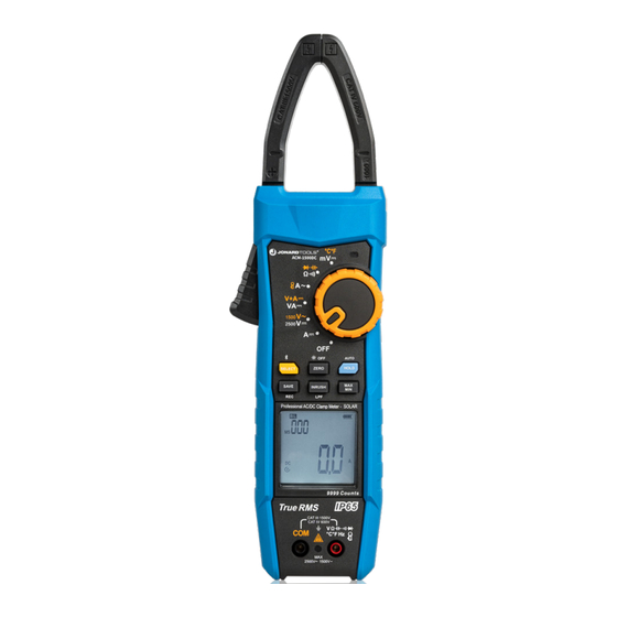
- Page 1 ACM-1500DC SOLAR + CLAMP METER CAT III 1500 V INSTRUCTION MANUAL...
- Page 2 Preface Thank you for purchasing the ACM-1500DC Solar+ Clamp Meter CAT III 1500 V. In order to use this product safely and correctly, please read this manual thoroughly, especially the “Safety Information” section. Limited Warranty and Liability This product will be free from defects in material and workmanship for one year from the date of purchase.
-
Page 3: Table Of Contents
ACM-1500DC Instruction Manual TABLE OF CONTENTS Overview ..............3 Features ............... 3 III. Accessories ..............4 Safety Information ............4 Electrical Symbols ............6 General Characteristics ..........7 VII. External Structure ............8 VIII. Rotary Switch .............. 9 Button Functions ............10 LCD Display .............. -
Page 4: Overview
Bluetooth function, which enable remote control and monitoring on the measurement data via the “ACM-1500DC” APP. The ACM-1500DC is an ideal meter for installation and maintenance in the photovoltaic field. This Clamp Meter can also be applied in the energy storage system, UPS (uninterrupted power supply), large-scale motor, and other high voltage environments. -
Page 5: Accessories
ACM-1500DC Instruction Manual III. ACCESSORIES Please carefully check if any accessory below is missing or damaged. User manual: 1 pc Test leads: 1 pair Carrying case: 1 pc Warranty certificate: 1 pc AA 1.5V battery: 2 pcs Please contact your local distributor if any accessory is missing or damaged. - Page 6 Before measuring in-circuit resistance, diode, circuit, please disconnect all powers in the circuit of measured object and discharge all capacitors thoroughly. Do not use the product in a circuit with voltage over the rated value. To avoid electric shock, please disconnect the test probe from the measured circuit before opening the battery cover or rear cover.
-
Page 7: Electrical Symbols
ACM-1500DC Instruction Manual ELECTRICAL SYMBOLS Symbol Description Do not place equipment and its accessories in trash. Items must be properly disposed of in accordance with local regulations. Double Insulated AC (Alternating Current) DC (Direct Current) Grounding Warning Application around and removal from UNINSULATED HAZARDOUS LIVE conductors is permitted. -
Page 8: General Characteristics
VI. GENERAL CHARACTERISTICS • Display count: 9999 • Polarity indication: Auto • Overload indication: “OL” or “-OL” • Low battery indication: The symbol “ ” appears on the LCD to indicate the battery voltage is lower than the working voltage. Please replace the batteries with new ones in time. •... -
Page 9: External Structure
ACM-1500DC Instruction Manual VII. EXTERNAL STRUCTURE ( Figure 1 ) Figure 1 Clamp jaw Light-guide area for infrared Tactile barrier transmission Trigger Signal input terminal Functional buttons (connected with red test lead) LCD display Rotary switch COM terminal (connected Light-sensitive area... -
Page 10: Rotary Switch
VIII. ROTARY SWITCH ( Figure 2 ) Figure 2 Position Description Power off DC current measurement V / V AC/DC voltage measurement VA /V + A DC power measurement/DC voltage + DC current measurement AC current measurement (clamp jaws) / Ω / Continuity/resistance/diode/capacitance measurement mV /°C°F mV AC/DC current measurement/Temperature measurement... -
Page 11: Button Functions
ACM-1500DC Instruction Manual IX. BUTTON FUNCTIONS ( Figure 3 ) Short press: Press for < 2 seconds / Long press: Press for ≥ 2 seconds Figure 3 Button Description Short press: 1. DCV/ACV position: Short press to select DCV and ACV positions cyclically. - Page 12 IX. BUTTON FUNCTIONS ( cont’d ) Short press: Press for < 2 seconds / Long press: Press for ≥ 2 seconds Button Description Short press to zero the residual reading of DCA. Long press to turn ON/OFF the automatic backlight function. Short press to turn ON/OFF the data hold mode.
-
Page 13: Lcd Display
ACM-1500DC Instruction Manual LCD DISPLAY ( Figure 4 ) Figure 4 Bluetooth 14. Low pass filter 25. Temperature Auto-save data 15. INRUSH measurement (sub-display) Clearing storage data 16. Resistance unit 26. Low battery Recording data 17. Voltage unit 27. Displayed value MAX/MIN/Average 18. -
Page 14: Operating Instructions
XI. OPERATING INSTRUCTIONS Please check the built-in batteries (AA 1.5V × 2) before use. If low battery occurs after the Clamp Meter is turned on, the symbol “ ” will be displayed on the LCD. To ensure measurement accuracy, please replace the batteries in time. The warning symbol “ ”... - Page 15 ACM-1500DC Instruction Manual To start the ACV-LPF function, long press the INRUSH button when measuring ACV. In A CV-LPF function, the composite sine signal generated by the inverter and variable-frequency motor can be measured (as shown in the image below).
- Page 16 Set the rotary switch to “V + A /VA ”, short press the SELECT button to switch to VA or V+A function, connect (in parallel) the test leads with the source or load to be measured, press and hold the trigger to open the clamp jaws, clamp the conductor to be measured, then release the trigger slowly to close the clamp jaws completely.
- Page 17 ACM-1500DC Instruction Manual button again to exit the INRUSH and peak measurement function (as shown in the image below). WARNING • Measure only one current conductor at a time. Otherwise the measurement result will be incorrect. • To ensure an accurate measurement result, please set the measured conductor at the center of...
- Page 18 10 Hz~100 Hz: ≥ 5 A 100 Hz~999.9Hz: ≥ 10 A • The error specified by the flex current sensor is the intrinsic error of ACM-1500DC. RESISTANCE MEASUREMENT ( Figure 10 ) Connect the red test lead to “V” terminal and black to “COM”.
- Page 19 ACM-1500DC Instruction Manual SELECT button to switch to the diode measurement position. The polarity of red test lead is “+” and black is “-”. Connect the red test lead to the positive pole of the measured diode and black to negative.
- Page 20 Connect the red test lead to “V” terminal and black to “COM”. °C°F Set the rotary switch to “ ”, short press the SELECT button to switch to DCmV measurement mode, then connect (in parallel) the test leads with the source or load to be measured.
-
Page 21: Other Functions
• Long press the SELECT button to turn on/off the Bluetooth. If the Clamp Meter with the Bluetooth on fails to connect with the APP, the Bluetooth symbol on the LCD will blink. Open the “ACM-1500DC” APP, search ACM-1500DC, make connection, and then perform data communication, button control and other operations. -
Page 22: Technical Specifications
XIII. TECHNICAL SPECIFICATIONS Accuracy: ± (a% of rdg. + b dgt.); guaranteed for 1 year Ambient temperature and humidity: 23°C ± 5°C; ≤ 80% RH Temperature coefficient: The temperature condition to ensure accuracy is 18°C~28°C. The fluctuation range of ambient temperature keeps within ± 1°C. If the temperature is < 18°C or > 28°C, the additional error of temperature coefficient is 0.1 ×... - Page 23 ACM-1500DC Instruction Manual 3. AC Voltage (ACV) a.) ACV Range Resolution Accuracy Overload Protection 999.9V 0.1V ± (1.0%+5) 2500V DC/1500V AC 1500V b.) ACV-LPF Range Resolution Accuracy Overload Protection ± (2.0%+9) 999.9V 0.1V 2500V DC/1500V AC (45Hz~100Hz) • Input impedance: About 2 MΩ...
- Page 24 4. DC Power (VA) Range Resolution Accuracy Overload Protection 999.9KVA 0.1KVA 2500V DC/1500V AC ± (2.0%+20) 1000A AC/DC 2500KVA 1KVA • Precision range: 5~100% of range 5. AC Current (ACA) a.) ACA Range Resolution Accuracy Overload Protection ± (2.0%+5) (40Hz~100Hz) 999.9A 0.1A 1000A AC/DC...
- Page 25 ACM-1500DC Instruction Manual b.) Add 5% for crest factor of 2~2.5 c.) Add 7% for crest factor of 2.5~3 • Perform measurement at the center of the clamp jaws. An error of 1% is added if deviated from the center.
- Page 26 8. Capacitance Range Resolution Accuracy Overload Protection 100.0µf 0.1µf ± (1.0%+5) 2500V DC/1500V AC 1000µf 1µf • Residual reading under open-circuit condition: ≤ 5 digits • Measured value = Displayed value - Residual reading • Precision range: 5~100% of range Table of Auto Hold Function Function Threshold...
-
Page 27: Bluetooth
For iOS 3. Usage Open the Bluetooth functions of both the Clamp Meter and mobile phone, tap the “ACM-1500DC” APP icon on your phone desktop to open the software, the software then enters the navigation interface and searches nearby Bluetooth-enabled meters automatically. After that, select the corresponding meter and make connection. -
Page 28: Maintenance
XV. MAINTENANCE WARNING To avoid electric shock, please remove the test leads before opening the bottom cover. If the Clamp Meter is not in use, please turn it off to avoid consuming battery power continuously. General maintenance: a.) The maintenance and service must be performed by qualified maintenance personnel or designated service center.
Need help?
Do you have a question about the ACM-1500DC and is the answer not in the manual?
Questions and answers