Table of Contents
Advertisement
Quick Links
Operation
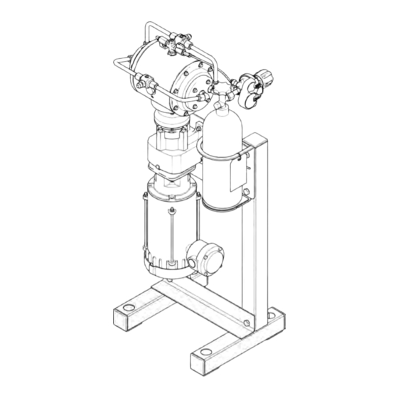
MODEL MVP-150
VAPOR RECOVERY PUMP
Designed for hydrocarbon extraction processing.
For LP-Gas Recovery
Electric-Powered
Dual-Diaphragm
Hazardous Location Motor
Stainless Steel Wetted Parts
Rated Maximum Allowable
Withstand Pressure (MAWP): LPG-375-PSI
For professional use only.
Important Safety Instructions
Read all warnings and instructions in this manual
and in the pump Repair/Parts manual before using
the equipment.
Save these instructions.
3A6339B EN
Advertisement
Table of Contents

Related Manuals for Master MVP-150


Summary of Contents for Master MVP-150
- Page 1 Operation MODEL MVP-150 VAPOR RECOVERY PUMP 3A6339B EN Designed for hydrocarbon extraction processing. For LP-Gas Recovery Electric-Powered Dual-Diaphragm Hazardous Location Motor Stainless Steel Wetted Parts Rated Maximum Allowable Withstand Pressure (MAWP): LPG-375-PSI For professional use only. Important Safety Instructions Read all warnings and instructions in this manual and in the pump Repair/Parts manual before using the equipment.
-
Page 2: Table Of Contents
Model Model Motor Motor Motor Pump Pump Pump Cylinder Cylinder Cylinder 2 2 2 MVP-150-1PH 2 HP 1-Phase MVP-150-3PH 2 HP 3-Phase MVP-150-ATEX Related Manuals Manuals Related Related Manuals Manual Number Title 3A6340 Model MVP-150 Vapor Recovery Pump, Repair/Parts 3A6339B... -
Page 3: Approvals
Approvals Approvals Approvals Approvals Approvals Approvals Approvals Motors on pump models MVP-150- Class I Group C&D, Class II Group F&G, T3B 1PH, MVP-150-3PH certified to: Pump model MVP-150-ATEX certified to: II 2 G Ex d h IIB T3 Gb 3A6339B... -
Page 4: Warnings
Warnings Warnings Warnings Warnings The following warnings are for the setup, use, grounding, maintenance, and repair of this equipment. The exclamation point symbol alerts you to a general warning and the hazard symbols refer to procedure-specific risks. When these symbols appear in the body of this manual or on warning labels, refer back to these Warnings. - Page 5 Warnings WARNING EQUIPMENT EQUIPMENT EQUIPMENT MISUSE MISUSE MISUSE HAZARD HAZARD HAZARD Misuse can cause death or serious injury. • Do not operate the unit when fatigued or under the influence of drugs or alcohol. • Do not exceed the maximum working pressure or temperature rating of the lowest rated system component.
- Page 6 Warnings WARNING BURN BURN BURN HAZARD HAZARD HAZARD Equipment surfaces can become very hot during operation. To avoid severe burns: • Do not touch hot equipment. PERSONAL PROTECTIVE PROTECTIVE EQUIPMENT EQUIPMENT PERSONAL PERSONAL PROTECTIVE EQUIPMENT Wear appropriate protective equipment when in the work area to help prevent serious injury, including eye injury, hearing loss, inhalation of fumes, and burns.
-
Page 7: General Information
General Information General Information Information General General Information The Typical Installation shown is only a guide for selecting and installing system components. Contact your MVP distributor for assistance in planning a system to suit your needs. Always use Genuine MVP Install all products in accordance with manufacturer’s Parts and Accessories. -
Page 8: Installation
Installation Installation Installation Installation Tighten Fasteners Fasteners Tighten Tighten Fasteners • Motor: Motor: Motor: Motors have a ground screw in the electrical box. Use the ground screw to ground the motor to the electrical system. Before using the pump, check and retorque all external fasteners. -
Page 9: Pressure Gauges
Installation Pressure Gauges Gauges Pressure Pressure Gauges A pressure gauge may be added at the inlet tee, outlet tee, and center section fittings. Use liquid-filled gauges with stainless steel wetted parts and 1/4 in. npt(m) threads. Electrical Electrical Electrical Connections Connections Connections NOTE:... - Page 10 Installation For 240V 240V Wiring: Wiring: Connect wire L1 to U1, L2 to 7. Close the motor electrical box. Torque the 5. For 240V Wiring: screws to 20 in-lb (2.3 N•m). V1, and L3 to W1. Bridge as follows. Wire Connections Connections at at at the the ATEX ATEX Motor...
-
Page 11: Operation
Operation Operation Operation Operation Tighten Fasteners Fasteners Tighten Tighten Fasteners NOTE: NOTE: Keep the vent valve open until gas NOTE: flow starts to slow. Before using the pump, check and b. Close the center section vent valve. retorque all external fasteners. Follow 5. -
Page 12: Pressure Relief Procedure
Operation Pressure Relief Relief Procedure Procedure Pressure Pressure Relief Procedure 3. Close the shutoff valve on the CO cylinder. 4. On CO port (E), open the pump CO bleed valve Follow the Pressure Relief Procedure and CO supply valve. whenever you see this symbol. NOTE: NOTE: NOTE: In the event of a diaphragm rupture,... -
Page 13: Maintenance
Maintenance Maintenance Maintenance Maintenance Maintenance Schedule Schedule Maintenance Maintenance Schedule NOTE: Cover and cap screws have a thread-locking NOTE: NOTE: adhesive patch applied to the threads. If this patch is excessively worn, the screws may loosen during Establish a preventive maintenance schedule operation. -
Page 14: Dimensions
Dimensions Dimensions Dimensions Dimensions Ref. Inches A A A 20.0 50.8 B B B 46.0 116.8 C C C 41.0 104.0 D D D 15.0 38.1 E E E 17.0 43.2 F F F 17.8 G G G 17.3 H H H 19.9 50.5 J J J... -
Page 15: Technical Data
Electric Electric Motor: Explosionproof hazardous areas (see approvals page) Model MVP-150-3PH, inverter rated Power 2 Hp 1.5 kW Speed 3600 rpm (60 Hz) Gear Ratio 16.5:1 Voltage 3–phase 208-230/460V Maximum Amperage Load 5.2 A (230V) / 2.6 A (460V) - Page 16 Technical Data Metric Metric Metric 80.5 dBa Sound Pressure [tested 3.28 ft (1 m) from equipment] Materials Materials Materials Process Pressure Section and Reed Valves stainless steel Diaphragms standard: PTFE optional: FKM fluoroelastomer Process Vapor Temperature Range FKM: -40° to 275°F (-40° to 135°C) PTFE: +40°...
- Page 17 Notes Notes Notes Notes 3A6339B...
-
Page 18: Mvp Standard Warranty
MVP reserves the right to make changes at any time without notice. Original Instructions. This manual contains English. MM 3A6339 MVP Headquarters: Headquarters: Santa Cruz Headquarters: Master Vapor Vapor Pumps Pumps LLC LLC • • • 849 849 Almar Almar Ave., Ave., Suite...
Need help?
Do you have a question about the MVP-150 and is the answer not in the manual?
Questions and answers