Table of Contents
Advertisement
Quick Links
Repair/Parts
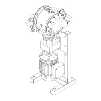
MODEL MVP-150XL
VAPOR RECOVERY PUMP
Designed for hydrocarbon extraction processing.
For LP-Gas Recovery
Electric-Powered
Dual-Diaphragm
Hazardous Location Motor
Stainless Steel Wetted Parts
Rated MAWP: LPG-375-PSI
For professional use only.
Important Safety Instructions
Read all warnings and instructions in this manual
and in the pump Repair/Parts manual before using
the equipment.
Save these instructions.
3A7034A
EN
Advertisement
Table of Contents

Related Manuals for Master MVP-150XL


Summary of Contents for Master MVP-150XL
- Page 1 Repair/Parts MODEL MVP-150XL VAPOR RECOVERY PUMP 3A7034A Designed for hydrocarbon extraction processing. For LP-Gas Recovery Electric-Powered Dual-Diaphragm Hazardous Location Motor Stainless Steel Wetted Parts Rated MAWP: LPG-375-PSI For professional use only. Important Safety Instructions Read all warnings and instructions in this manual and in the pump Repair/Parts manual before using the equipment.
-
Page 2: Table Of Contents
5 HP Related Manuals Manuals Related Related Manuals Manual Number Title 3A6887 Model MVP-150XL Vapor Recovery Pump, Operation Approvals Approvals Approvals Approvals Approvals Approvals Class I – Div. I – Group C and D, T3C Motors on pump model 25M869 certified to: Class I –... -
Page 3: Warnings
Warnings Warnings Warnings Warnings The following warnings are for the setup, use, grounding, maintenance, and repair of this equipment. The exclamation point symbol alerts you to a general warning and the hazard symbols refer to procedure-specific risks. When these symbols appear in the body of this manual or on warning labels, refer back to these Warnings. - Page 4 Warnings WARNING PRESSURIZED EQUIPMENT EQUIPMENT HAZARD HAZARD PRESSURIZED PRESSURIZED EQUIPMENT HAZARD Vapor or solvent from the equipment, leaks, or ruptured components can splash in the eyes or on skin and cause serious injury. Pressure Relief Relief Procedure Procedure when you stop operation and before cleaning, •...
- Page 5 Warnings WARNING LP- - - GAS GAS HAZARD HAZARD HAZARD LP-Gas can cause serious injury or death if splashed in the eyes or on skin, inhaled, or ignited. • Read Safety Data Sheet (SDS) to know the specific hazards of the solvents you are using. •...
-
Page 6: Troubleshooting
Troubleshooting Troubleshooting Troubleshooting Troubleshooting • Follow the Pressure Relief Procedure, page 7 before checking or servicing the equipment. • Check all possible problems and causes before disassembly. Problem Cause Solution Problem Problem Cause Cause Solution Solution Pump cycles but will not prime and/or Pump head center section has no Check CO supply, adjust CO... -
Page 7: Repair
Repair Repair Pressure Relief Relief Procedure Procedure Repair Repair Pressure Pressure Relief Procedure Follow the Pressure Relief Procedure whenever you see this symbol. To avoid serious injury or death from fumes or fluids, never move or lift a pump under pressure. If dropped, the center section may rupture. -
Page 8: Check Valve Repair
Repair Check Valve Valve Repair Repair Check Check Valve Repair 4. Use a screwdriver to remove the outlet check valve screw. Manifold tubing may become hot during operation. Prior to removal, ensure that tubing has cooled enough to handle safely. 1. -
Page 9: Diaphragm Repair
Repair Diaphragm Repair Repair Diaphragm Diaphragm Repair Manifold tubing may become hot during operation. Prior to removal, ensure that tubing has cooled enough to handle safely. Disassemble the the Diaphragms Diaphragms Disassemble Disassemble Diaphragms NOTE: Diaphragm kit is available. See Parts section. NOTE: NOTE: 1. - Page 10 Repair Reassemble Reassemble Reassemble the the Diaphragms Diaphragms Diaphragms 9. Attach the diaphragm covers and vapor caps. Apply medium-strength (blue) thread locker to the screw threads. See Torque Instructions, page to tighten. TIP: TIP: TIP: If you are also repairing or servicing the center section (drive shaft, piston, etc.), see Center Section Repair, page 11, before you put the...
-
Page 11: Center Section Repair
Repair Center Section Section Repair Repair Center Center Section Repair e. The shaft coupler (113) might come out with the drive shaft assembly. If not, reach into the alignment housing (116) and remove the shaft coupler (113). Remove the seal cartridge, o-ring (109) and the radial seal (111) with o-ring (111a) from Disassemble the the Center... - Page 12 Repair Reassemble Reassemble Reassemble the the Center Center Center Section Section Section 1. Clean and dry the center housing (101), the 4. Install the drive shaft: center of the piston (105) and the drive shaft a. Be sure the sealing surface of the drive shaft (109).
- Page 13 Repair Apply medium-strength (blue) thread locker to threads. Torque to 15–25 ft-lb (20–34 N•m). Lips must face IN IN IN toward the center. Apply anti-seize lubricant liberally on the radial surfaces of the drive shaft assembly. Install the drive shaft assembly with the groove facing up.
- Page 14 Repair Disconnect Disconnect Disconnect the the Motor Motor Motor and and Gearbox Gearbox Gearbox NOTE: NOTE: NOTE: Normally, the motor remains connected to the 3. Pull the motor (130d) straight off of the gearbox gearbox. Disconnect the motor only if you suspect (130a).
-
Page 15: Torque Instructions
Torque Instructions Torque Instructions Instructions Torque Torque Instructions If diaphragm cover or vapor cap fasteners have been loosened, it is important to torque them using the following procedure to improve sealing. NOTE: Cover and cap screws have a thread-locking NOTE: NOTE: adhesive patch applied to the threads. - Page 16 Notes Notes Notes Notes 3A7034A...
-
Page 17: Parts
Parts Parts Parts Parts 3A7034A... - Page 18 Parts Parts/Kits Quick Quick Reference Reference Parts/Kits Parts/Kits Quick Reference Use this table as a quick reference for kits. Go to the kit table on page 20 for a full description of kit contents. Description Qty. Qty. Qty. Description Qty. Qty.
- Page 19 Parts Drive Section Section Drive Drive Section 3A7034A...
- Page 20 Parts Kit Table Table Table Kit Ref Description Description Description HOUSING, center, Qty. Ref. Ref. Ref. Kit Description Description Description Qty. Qty. assembly; includes plugs 203 25R035 Kit, coupler, includes:Ref 115 O-RING, 374, Buna-N 204 25R036 Kit, shaft assembly, includes: RING, chamber Ref 107, 107a, 108, 109 1 ea...
-
Page 21: Technical Data
Technical Data Technical Data Data Technical Technical Data Metric Metric Metric Model Model Model MVP MVP- - - 150 150 Vapor Vapor Recovery Vapor Recovery Recovery Pump Pump Pump LP-Gas vapor recovery rate 18 cfm /min Butane recovery rate 3-4.5 lb/min 1.3-2 kg/min Butane recovery and re-condense rate 35-50 GPH... -
Page 22: Mvp Standard Warranty
MVP reserves the right to make changes at any time without notice. Original Instructions. This manual contains English. MM 3A7034 MVP Headquarters: Headquarters: Santa Cruz Headquarters: Master Vapor Vapor Pumps Pumps LLC LLC • • • 849 849 Almar Almar Ave., Ave., Suite...
Need help?
Do you have a question about the MVP-150XL and is the answer not in the manual?
Questions and answers