Table of Contents
Advertisement
Advertisement
Table of Contents

Related Manuals for Eurosets ECMOLIFE


Summary of Contents for Eurosets ECMOLIFE
- Page 1 ECMOLIFE SYSTEM INSTRUCTIONS FOR USE EU10583_ENG Rev.12 - 2023-04-03...
-
Page 2: Table Of Contents
3.6. LOGICAL PRESSURE TRANSDUCER AND SMITH MEDICAL PRESSURE SENSOR CONNECTION TO THE ECMOLIFE CONSOLE ............................23 3.7. EDWARDS PRESSURE SENSOR CONNECTION TO THE ECMOLIFE CONSOLE ........24 4. DISPOSABLE CENTRIFUGAL PUMP AND OXYGENATOR SETUP ..............25 5. ECMOLIFE DRIVER MOTOR HOLDER AND SETUP ..................26 6. - Page 3 8.2.5. ALARM PAUSE ............................55 8.2.6. ALARM ACKNOWNLEDGE........................55 8.3. ALARMS TABLE ..............................55 9. PRIMARY UNIT: COMBINATION SYSTEM ECMOLIFE-COLIBRÌ (Valid only for device with the Colibrì connector on the front panel) ..............................56 9.1. ECMOLIFE-COLIBRÌ CONNECTION ........................ 57 9.2. FUNCTIONALITIES ............................59 9.2.1.
- Page 4 14. TECHNICAL SPECIFICATIONS ........................83 15. ELECTROMAGNETIC COMPATIBILITY ......................86 16. MAINTENANCE - SERVICING - SYSTEM LIFESPAN ..................87 16.1. LIFECYCLE OF THE RECHARGEABLE INTERNAL BATTERY ..............87 16.2. PERIODICAL MAINTENANCE PROGRAM ....................87 16.3. BATTERY REPLACEMENT .......................... 88 16.4. POSSIBLE ANOMALIES OCCURRING DURING DEVICE FUNCTIONING ..........89 16.5.
-
Page 5: General Informations
DISPOSABLE CENTRIFUGAL PUMP: Magnetic non-occlusive blood pump consisting in a rotating impeller arranged with vanes inside a plastic housing with inlet and outlet ports. Blood is moved by centrifugal force with bearing-less magnetic levitation generated by ECMOLIFE System. HIGH PRIORITY ALARM: Indicates that immediate intervention by the OPERATOR is required. -
Page 6: Description
The organization responsible for the use and the maintenance of the device. The RESPONSIBLE ORGANIZATION can be, for example, a hospital or a medical practitioner. APPLIED PART: The part of the ECMOLIFE System which, under normal conditions of use, is in physical contact with the patient in order to fulfil its function. 1.3. DESCRIPTION ECMOLIFE System active medical device is composed by a programmable console (ECMOLIFE Console), a bearing- less motor driver (ECMOLIFE Motor driver) and sensors for blood parameters detection. -
Page 7: Contraindications
Emergency Room, Intensive Care Unit and during intra-hospital and inter-hospital patient transportation from one to another Unit or Hospital. ECMOLIFE System is intended to be used by qualified healthcare professionals specifically trained in the field of extracorporeal circulation: Perfusionists (Thoracic Cardiovascular Surgery - OR), Intensivists, ICU Nurses (ICU), Emergency physicians / Intensivists (ER), Cardiologist (CathLab). -
Page 8: General Warnings
• The Instruction for Use Manual is also provided on Eurosets website. • In case of incorrect visualization of Use Manual on Eurosets website. In addition, contact the technical • service. The device must be used in accordance with these instructions. EUROSETS cannot be held •... -
Page 9: Warnings For The Patient Transport
ECMOLIFE Centrifugal Pump standard model, present as standalone product ref. AG5078, or included in • perfusion tubing sets; ECMOLIFE Centrifugal Pump with Pdrain port located on blood inlet port, included in perfusion tubing sets only, • permanently connected with pressure monitoring probe;... -
Page 10: Symbols Description
1.14. SYMBOLS DESCRIPTION Symbol Explanation Symbol Explanation Manufacturer CLASS II equipment DEFIBRILLATION-PROOF TYPE CF Date of manufacture APPLIED PART Serial number Atmospheric pressure limitation Catalogue number Temperature limit Do not use if package is damaged and Humidity limitation consult instructions for use This way up On/Off (Push/push) Fragile, handle with care... -
Page 11: Transport And Storage Conditions
For storage and transport conditions refer to paragraph TECHNICAL SPECIFICATIONS. 1.16. LIMITED WARRANTY The ECMOLIFE System is guaranteed for 12 months from the date of purchase as long as the device has not been modified and/or tampered with by unauthorized persons. -
Page 12: System Components
2. SYSTEM COMPONENTS 2.1. GENERAL DEVICE DESCRIPTION ECMOLIFE System is composed by: EU5085 - Console EU10566 – Motor driver EU10574 – Bubble sensor EU6727 - AUXILIARY AIR/FLOW SENSOR PROBE 3/8x3/32 (Valid only for device with the Colibrì connector on the... - Page 13 EU6729 - AUXILIARY AIR/FLOW SENSOR PROBE 1/4’’x3/32’’ (Valid only for device with the Colibrì connector on the front panel) EU3896 – Venous probe EU1900 – Clamp on transducer SCT 3/8” x 3/32” EU1901 – Clamp on transducer SCT 1/4” x 3/32”...
- Page 14 EU6726 - ECMOLIFE FLOWMETER 3/8’’x3/32’’ (Valid only for device with the Colibrì connector on the front panel) EU6726 - ECMOLIFE FLOWMETER 1/4’’x3/32’’ (Valid only for device with the Colibrì connector on the front panel) MX960P1 – Logical pressure transducer EU3895 – Smith medical pressure cable...
- Page 15 EU1900 - Clamp on transducer SCT 3/8” x 3/32” or EU1901 – Clamp on transducer SCT 1/4” x 3/32” or EU6726 • - ECMOLIFE FLOWMETER 3/8’’x3/32’’ or EU6726 - ECMOLIFE FLOWMETER 1/4’’x3/32’’: Blood flow (LPM), Pump speed (RPM), EU3895 - Smith medical pressure cable with MX960P1 – Logical pressure transducer or EU6734 - Cable •...
-
Page 16: Console
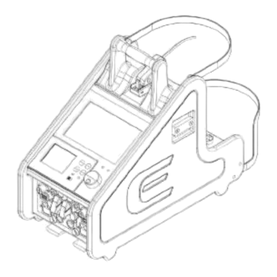
2.2. CONSOLE The console parts are assembled as shown below: 1. ECMO Module 2. ECMOLIFE Pressure sensor 3. Disposable Centrifugal Pump 4. ECMOLIFE Motor driver 5. ECMOLIFE Venous probe 6. ECMOLIFE Bubble sensor 7. ECMOLIFE Flowmeter 8. Tubing set... - Page 17 The console functioning can be managed through these panels: 1. Front panel 2. Rear panel ECMOLIFE System is featured by an integrated backup system, defined as backup unit. Added to the primary system, it acts as a replacement of the primary unit if this fails or it’s damaged.
-
Page 18: Front Panel
2.2.1. FRONT PANEL On the front panel two separated areas are identified: Primary Unit on the left side while Backup Unit on the right side. Warning Make sure that the power supply is available and the battery charge is full. •... -
Page 19: Rear Panel
2.2.2. REAR PANEL The rear panel is composed by: 1. Pressure sensor P socket; drain 2. Pressure sensor P socket; 3. Pressure sensor P socket; 4. Venous probe sensor socket; 5. Air Bubble sensor socket; 6. Pressure sensor P3to1 socket; 7. -
Page 20: Sensors Setup On Tubing
3. SENSORS SETUP ON TUBING 3.1. DISPOSABLE CUVETTE FOR VENOUS PROBE AND CONNECTION ON TUBING SET The Venous Probe shall be used only in conjunction with the 3/8” – 3/8” or 1/4 – 1/4’’ disposable polycarbonate cuvette to be installed in the venous line tubing. The cuvette is available both with and without internal phosphorylcholine coating. For a proper cuvette connection, tubing size shall be 3/8”... -
Page 21: Venous Probe Connection Onto The Disposable Cuvette
3.2. VENOUS PROBE CONNECTION ONTO THE DISPOSABLE CUVETTE To connect the venous probe onto the disposable cuvette press it onto the cuvette until retaining tabs click is heard signaling the probe is locked in place as shown below. Check that the sensor probe is properly and securely attached to the cuvette. Venous probe correctly installed onto the cuvette Venous probe incorrectly installed onto the cuvette Remove venous probe from cuvette by pressing the retaining tabs with the fingers. -
Page 22: Clamp-On Transducer (Flowmeter) Connection On The Tubing
15cm straight tube before and after the transducers. Check the indications on the EUROSETS tubing set in order to identify the suggested flowmeter positioning in order to minimize the flow turbulence and the associated measurement inaccuracies related to the sensor. -
Page 23: Logical Pressure Transducer And Smith Medical Pressure Sensor Connection To The Ecmolife Console
During the insertion the operator shall hear a click sound. Insert the cable to the relevant pressure connector (Pin – Pout –Pdrain) on ECMOLIFE console. For the assembly of Single use MEDEX (Smith Medical) pressure transducer refer to relevant instructions for use. -
Page 24: Edwards Pressure Sensor Connection To The Ecmolife Console
3.7. EDWARDS PRESSURE SENSOR CONNECTION TO THE ECMOLIFE CONSOLE Insert the cable to the relevant pressure connector (Pin – Pout –Pdrain) on ECMOLIFE console. For the assembly of Single use EDWARDS Pressure transducerr refer to relevant instructions for use. Ref. -
Page 25: Disposable Centrifugal Pump And Oxygenator Setup
4. DISPOSABLE CENTRIFUGAL PUMP AND OXYGENATOR SETUP 1. Exctract the ECMOLIFE disposable set from the package and lock the Oxygenator plastic holder to the four bracket pins 2. Ensure the ECMOLIFE Centrifugal System is ready, electrically connected with mains and flowmeter plugged in. -
Page 26: Ecmolife Driver Motor Holder And Setup
5. ECMOLIFE DRIVER MOTOR HOLDER AND SETUP 1. Extract the “EU2511 Ecmolife holder motor driver” from the package and use the central knob (A) to loose or tight the holder in the desired position 2. Use the front knob (B) to attach the holder motor driver to the pole... -
Page 27: Display
• Check the activation of Alarm LED. In case of failure in the activation the use of the device must be • interrupted. Eurosets disclaims the relevant risk of a use of a device with backup section not tested. •... -
Page 28: Primary Unit
7. PRIMARY UNIT 7.1. DISPLAY STATUS BAR On the top of touchscreen there is the status bar with the following settings: 1. Date and Time; 2. Title of the active page; 3. Charge status Symbol and remaining time; 4. Main power supply indicator: connected / disconnected. The status bar color indicates priority of ongoing alarm: Color Priority... - Page 29 Secondary settings The right section is dedicated to secondary and/or browsing parameters. During the navigation into the several sections provided by toolbar, this section will be relocated in the upper part of central area so that the data is ALWAYS displayed. Main buttons In the center of the screen the following buttons are displayed: +/- buttons: to increase/decrease parameters value;...
- Page 30 Toolbar At the bottom of the touchscreen, the toolbar collects the main features provided by the device: 1. Main screen 2. Edit patient data 3. Alarms 4. Download 5. Sensors 6. Settings 7. Graphs 8. Colibrì...
-
Page 31: Toolbar
7.2. TOOLBAR MAIN SCREEN Through the main screen menu you can set primary treatment parameters (section A) as blood flow (LPM) and pump rotation speed (RPM) and you can track secondary settings (section B) sampled through pressure sensors and venous probe. EDIT PATIENT DATA On the Edit Patient Data screen, you can fill all the patient information by selecting the... - Page 32 ALARMS In this section you can enter the Alarm Menu: Using Alarm Menu you can manage: Alarm Settings Menu, Alarm List Menu. In Alarm Settings Menu you can configure alarm ranges of treatment parameters where you can establish alarms minimum and maximum threshold value.
- Page 33 DOWNLOAD In this section you can download the patient data and save it into any memory drive by connecting an USB key to the Primary USB key connection in the front panel. During the treatment, is possible to download the last treatment performed and/or the treatment ongoing.
- Page 34 Probe correction In this section you can apply correction of the parameters values currently detected by the venous probe compared to reference system such as a gas analyzer. Zero pressure In this section you can adjust pressure sensors to zero. Caution Zero adjustment shall be performed only when pressure values fall within -200/+200...
- Page 35 SETTINGS In the Settings screen you can modify the following options: Language Date/Time Brightness & Volume System Display Service (not available during treatment) Language Select language. Date/Time Flow Control Change date and time info. Activate/deactivate the Blood Flow (LPM) Mode control. Brightness &...
- Page 36 GRAPHS In this section you can visualize the real time parameters trend. The graphs of follow parameters are available: Blood Flow (LPM) • Pump Speed (RPM) • Pre-oxygenator pressure (Pin) • Post-oxygenator pressure (Pout), • Venous oxygen saturation (SvO2), • Pressure drop (ΔP) •...
-
Page 37: Parameters
± 7% for flow value > 1.0 3/32” l/min EU6726 - ±0.05 l/min for flow value Detected blood ECMOLIFE <= 1.0 l/min Blood flow 0,0 ÷ 10,0 flow speed FLOWMETER ± 5% for flow value > 1.0 3/8’’x3/32’’... - Page 38 Inlet pressure in MX960P1 Logical oxygenator pressure transducer mmHg module and + EU3895 smith -200 ÷ +800 (convertible ± 5% outlet pressure medical pressure in kPa) from driver sensor engine ± 10mmHg for pressure value < -50 mmHg Inlet pressure in ±...
- Page 39 PARAMETERS EDITING Parameters selection You can activate the parameter selection by pushing on the display the value that you want to modify, for at least 1 second. Increase and decrease parameters value By turning the knob clockwise (+) or anticlockwise (-) or using the +/- display buttons, it is possible to increase / decrease the value of the selected parameter.
-
Page 40: Functionalities
For more details see Chapter 9 PRIMARY UNIT: COMBINATION SYSTEM ECMOLIFE_COLIBRÌ The Adult/Paediatric option allows to configure the device to manage the ECMOLIFE Centrifugal Pump with 3/8x3/32’’ tubing sets. The New Born option allows to configure the device to manage the NEW BORN Centrifugal Pump and 1/4X3/32’’... -
Page 41: Diagnostic Phase
7.4.2. DIAGNOSTIC PHASE In diagnostic screen the device will check all the sensors are properly connected. To start the diagnostic phase, press Start Autotest button. To retry the check, press Retry button. Each subsequent connection of probes or sensors in this phase or during the treatment shall be confirmed in the diagnostic page by clicking the Retry button. -
Page 42: Parameters Configuration Phase
7.4.3. PARAMETERS CONFIGURATION PHASE After the autotest phase, the device will inform you that a new configuration of device parameters, saved during the previous treatment, is available. If a saved configuration is available you can select between “Default Configuration” “Saved Configuration”. - Page 43 To create a new configuration, you can use the “SAVE” button in the following pages: Alarm settings, Display, Parameters, Brightness and volume. If you choose to start the device with the “Saved Configuration” of parameters, you will have the possibility to restore the Default configuration during the treatment using the “DEFAULT”...
-
Page 44: Priming Phase
START / STOP PROCEDURE You can select “START PRIMING” in order to start the automatic procedure. ECMOLIFE will set and hold for few minutes different RPM targets within the range 0-5000RPM. During this phase, the circuit will be automatically primed and the centrifugal pump impeller will be further verified in a self-learning procedure. - Page 45 START / STOP PROCEDURE You can select “START PRIMING” in order to start the automatic procedure. ECMOLIFE will set and hold for few minutes different RPM targets within the range 0-4500RPM. During this phase, the circuit will be automatically primed and the centrifugal pump impeller will be further verified in a self-learning procedure.
- Page 46 SKIP PROCEDURE – ADULT/PAEDIATRIC/NEW BORN CONFIGURATION In case of urgency you can SKIP the automatic procedure and complete the priming phase by manually setting the RPM from the main screen. Skipping the automatic procedure doesn’t allow the device to perform the impeller self-learning operation. For safety reason a RPM upper range limitation will be set for RPM values higher than 3500RPM and 4500RPM..
-
Page 47: Operating Mode
7.4.5. OPERATING MODE During the use of the device, the desired RPM or pump blood flow values can be set by the user. DRIVER RPM MONITORING MODE (DEFAULT MODE) Default mode allows to control the centrifugal pump RPM, the blood flow will adapt to the set RPM. RPM values can be set by rotating the knob or using the touch screen +/- buttons. -
Page 48: Blood Flow Monitoring Mode (Additional Mode)
7.4.6. BLOOD FLOW MONITORING MODE (ADDITIONAL MODE) Blood Flow control shall be disabled by default. Blood Flow control mode can be enabled by the Flow Control page in Settings device menu. Warning If you skip the automatic priming, the Blood Flow Control Mode will not be available until the first autocalibration, at 3450 RPM, is complete. -
Page 49: Lpm Control Enabled/Disabled Mode View
7.4.7. LPM CONTROL ENABLED/DISABLED MODE VIEW LPM control activation is shown by the visualization of a frame around the parameter. -
Page 50: Primary Unit - Alarms
8. PRIMARY UNIT - ALARMS 8.1. ALARM RANGE AND PARAMETERS It is possible to set the alarm limits in the Alarm screen. The alarm activates whenever the parameter value exceeds the warning limits, i.e: Value measured above the upper limit •... -
Page 51: Alarm Limit - Adult/Paediatric Configuration
8.1.1. ALARM LIMIT – ADULT/PAEDIATRIC CONFIGURATION Default Measure Alarm Parameter Description Sensor Measure unit alarm range threshold threshold Clamp on Detected blood flow Blod flow transducer Sct 3/8” 0,0 ÷ 10,0 0,0 ÷ 10,0 0,2 ÷ 8,0 speed x 3/32” Speed Speed revolutions 2000 ÷... -
Page 52: Alarm Limit - New Born Configuration
8.1.2. ALARM LIMIT – NEW BORN CONFIGURATION It is possible to set the alarm limits in the Alarm screen. The alarm activates whenever the parameter value exceeds the warning limits, i.e: Value measured above the upper limit • Value measured above the lower limit •... -
Page 53: Zero Flow Mode
8.1.3. ZERO FLOW MODE In order to avoid any kind of back flow once the user set a Blood Flow value = 0, the device automatically maintains a minimum rotation of the impeller (which may vary depending on the pressure detected at the Centrifugal Pump outlet line). -
Page 54: Air Bubble Detection Alarm (High Priority)
8.2.1. AIR BUBBLE DETECTION ALARM (HIGH PRIORITY) 8.2.2. BLOOD FLOW DETECTION ALARM (HIGH PRIORITY) 8.2.3. SECONDARY PARAMETERS ALARM (MEDIUM PRIORITY) 8.2.4. SECONDARY PARAMETERS ALARM (LOW PRIORITY) -
Page 55: Alarm Pause
8.2.5. ALARM PAUSE When an alarm is activated, on the main buttons section, the button is displayed in the "variable" button which allows the alarm sound to be silenced for 2 minutes. The visual alarm status is kept active until it is resolved or the alarm is deactivated for that specific parameter. -
Page 56: Primary Unit: Combination System Ecmolife-Colibrì (Valid Only For Device With The Colibrì Connector On The Front Panel)
9. PRIMARY UNIT: COMBINATION SYSTEM ECMOLIFE-COLIBRÌ (Valid only for device with the Colibrì connector on the front panel) It is possible to use the Primary section of ECMOLIFE console in combination with the Colibrì system (EU5096). Colibrì system is composed by: COLIBRÌ Console, COLIBRÌ Flowmeter and COLIBRÌ Power Module. -
Page 57: Ecmolife-Colibrì Connection
1. Move the lever of the COLIBRÌ bracket to the 'OPEN' position. 2. Insert the COLIBRÌ Bracket into the support plate on the wall of the ECMOLIFE Console facing the two stand poles. 3. Move the lever of the COLIBRÌ bracket to the 'CLOSED' position in order to fix the COLIBRI' Console on the ECMOLIFE Console. - Page 58 FUNCTIONAL CONNECTION Using the dedicate cable (ECMOLIFE-COLIBRÌ cable EU11108), you can connect the ECMOLIFE system to the Colibrì System as follow: 1. Using the Colibrì hanging system (B), fix the Colibrì System on the rear side of ECMOLIFE console. 2. Check the integrity of ECMOLIFE-COLIBRÌ...
-
Page 59: Functionalities
9.2. FUNCTIONALITIES 9.2.1. TURNING ON THE ECMOLIFE-COLIBRI’ SYSTEM In the Select Modality page of ECMOLIFE System select between “COLIBRÌ Configuration”. It is possible to connect the COLIBRI System to ECMOLIFE in any treatment phase. ECMOLIFE System is able to detect if the connection cable is connected to COLIBRI and if COLIBRI is turned off or turned on. -
Page 60: Diagnostic Phase
When the AUTOTEST is performed and the “Start Treatment” softkey is pressed, the ECMOLIFE System takes the control of COLIBRI treatment. When COLIBRI is connected to ECMOLIFE System, it is no longer possible to control the treatment through the COLIBRI screen: treatment flow and RPM information will be displayed, together with colibrì charge level. -
Page 61: Colibri Menu
9.2.4. COLIBRI MENU Through the COLIBRI menu page it is possible to check the COLIBRI connection status, the internal battery charge level and the external batteries charge level if connected to COLIBRI device. Through COLIBRI menu it is also possible to activate or deactivate the COLIBRI WIFI Module. -
Page 62: Alarms
Colibrì system is disconnected from Ecmolife but the connection cable is still connected to the Ecmolife console, the Ecmolife will continue to maintain the Colibrì internal battery level. From the Colibrì menu on Ecmolife it is possible to visualize the internal battery level of Colibrì device and the thunderbolt icon will inform if the Colibrì System is in charge. -
Page 63: Ecmolife-Colibrì Parameters Editing
The user can lock the ECMOLIFE display by pushing the lock button for at least 3 seconds. To enable the display, press at least 1sec the unlock button present in the footer bar of the ECMOLIFE screen or in the central bar of the ECMOLIFE main buttons. -
Page 64: Backup Unit
• Primary ECMOLIFE Motor driver • Backup Unit ECMOLIFE Console shall be activated, Backup Unit Motor driver installed and Backup Unit Flowmeter connected to allow fast switching to Backup Unit to safely continue the patient support. Warning Before starting the support, check that the Backup Unit battery is fully charged. -
Page 65: Toolbar
10.2. TOOLBAR MAIN SCREEN Through the main screen menu you can set primary treatment parameters as blood flow (LPM) and pump rotation speed (RPM) ALARMS In this section you can enter the Alarm Screen and configure RPM and LPM parameters alarm ranges where you can establish alarms minimum and maximum threshold value. - Page 66 DOWNLOAD In this section you can download the patient data and save it into any memory drive. During the treatment, it is possible to download the last treatment performed and/or the treatment ongoing. Before starting the treatment, it is possible to download the last treatment log file or the complete log file, with all the treatment data performed until then.
- Page 67 SETTINGS In the Settings screen you can modify the following options: Language Date/Time Brightness & Volume System Display Service (not available during treatment) Language Select language. Date/Time Flow Control Change date and time info. Activate/deactivate the Blood Flow (LPM) Mode control. Brightness &...
-
Page 68: Parameters
3/8” x 3/32” 10,0 ± 7% for flow value > 1.0 l/min ±0.05 l/min for flow Blood flow Detected blood ECMOLIFE FLOWMETER 0,0 ÷ value <= 1.0 l/min (Adult/Paediatric) flow speed 3/8’’x3/32’’ 10,0 ± 5% for flow value >... -
Page 69: Functionalities
10.4. FUNCTIONALITIES Backup Unit allows all the essential operations necessary to ensure the patient blood flow circulation. For this reason, only Flowmeter and Motor driver can be connected to the Backup Unit. Warning All the auxiliary sensors: Pressure Sensors • Venous Probe •... - Page 70 At the end of the diagnostic phase, by pressing the start treatment button the device is able to check the compatibility between the chosen configuration and the flow probe connected to the device. If the connected probe is not compatible with the chosen configuration, a dedicated warning is activated.
- Page 71 DRIVER RPM MONITORING MODE (DEFAULT MODE) Default mode allows to control the centrifugal pump RPM, the blood flow will adapt to the set RPM. RPM values can be set by using the panel +/- buttons. Edit confirmation or refusal It is necessary to confirm the set value by re-pushing the selected value on the display within at least 3 second. The parameter editing will be performed only if the user confirms.
- Page 72 BLOOD FLOW MONITORING MODE (ADDITIONAL MODE) Blood Flow control shall be disabled by default. Blood Flow control mode can be enabled by the Flow Control page in Settings device menù. When setting a new blood flow value, by increasing or decreasing it in the main parameters screen, the device will automatically adjust the RPM to reach the desired flow.
-
Page 73: Backup Unit - Alarms
11. BACKUP UNIT - ALARMS 11.1. ALARM RANGE AND PARAMETERS It is possible to set the alarm limits in the Alarm screen. The alarm activates whenever the parameter value exceeds the warning limits, i.e: Value measured above the upper limit •... -
Page 74: Alarms Priority
11.2. ALARMS PRIORITY Alarms activation depends strictly from the priority ranking of parameter involved, according to the following table. Priority Ranking Parameter Priority level Color Blood Flow High Pump Speed High 11.2.1. BLOOD FLOW DETECTION ALARM (HIGH PRIORITY) 11.2.2. ALARM PAUSE When an alarm is activated, on the main buttons section, the button is displayed in the "variable"... -
Page 75: Power Supply
12.2. EXTERNAL BATTERY During transport or in case main supply is not available, the device can be powered from the ECMOLIFE Auxiliary Battery kit EU3899 both from Primary and Backup section from their relevant external battery sockets (1-2). -
Page 76: Rechargeable Battery Autonomy
12.3. RECHARGEABLE BATTERY AUTONOMY In battery operation mode, in full charged condition, the guaranteed time for the device to function correctly is at least 90 min. The reported autonomy value is purely approximate, it may vary greatly due to different factors such as the number of connected sensors, the residual charge in the battery, the operating temperature, the natural decay of the battery over time, etc. -
Page 77: Supply Mode
12.5. SUPPLY MODE Mains power indicator Battery power indicator Description Mains power supply connected. Battery charging with indication of remaining battery. Mains power supply connected. No battery detected. Mains power supply not connected, battery operation with the indication of remaining battery. Mains power supply not connected, battery operation with the indication of remaining battery. -
Page 78: Intra-Hospital And Inter-Hospital Ecmolife Transportation
13. INTRA-HOSPITAL AND INTER-HOSPITAL ECMOLIFE TRANSPORTATION LEONARDO TROLLEY AND LEONARDO SLIM LEONARDO Trolley EU5093 and LEONARDO slim EU5094 are the trolley conceived to safely support and transport the ECMOLIFE CONSOLE during intra-hospital transport. Warning Consult the specific User Manuals/IFU EU10814 IFU Leonardo Trolley/IFU EU10814/S Leonardo Slim for the related technical data (weight, connections, etc.) and for its correct... - Page 79 ROAD AMBULANCE PLATE HOLDER ECMOLIFE Ambulance Plate Holder EU3898 is conceived to safely support and transport the ECMOLIFE CONSOLE during road ambulance transport through a dedicated hooking interface which can be easily adapted to the ambulance mounting rails. Warning Consult the specific User Manuals/IFU EU10831 IFU ECMOLIFE Plate Holder for the related technical data (weight, connections, etc.) and for its correct use.
- Page 80 24V Ambulance socket both on Primary and Backup section to their relevant external battery sockets (1-2). In order to avoid any electrical interference between ECMOLIFE device and ambulance on board systems The dedicated Ambulance Power Module interface EU3953 must be used.
- Page 81 Using its clip hanging system Ambulance Power Module can be mounted on the side rails of ECMOLIFE. Figures below describe module connectors 24V ECMOLIFE connector 24V Ambulance connector Warning Do not connect the ECMOLIFE 24V connection directly to the Ambulance 24V power source •...
- Page 82 FOIL STRETCHER HOLDER PLATE FOIL STRETCHER HOLDER PLATE EU3996 is conceived to safely support and transport the ECMOLIFE CONSOLE during road ambulance transport through a dedicated interface which can be located between the legs of the patient. Warning Consult the specific User Manuals/IFU EU11053 IFU FOIL for the related technical data...
-
Page 83: Technical Specifications
14. TECHNICAL SPECIFICATIONS Regulations Classification Classified in accordance with Regulation (EU) 2017/745 (MDR). IEC 60601-1:2005+AMD1:2012+AMD2:2020 ed.3 • IEC 60601-1-2: 2014+AMD1:2020 • IEC 60601-1-8:2006+AMD1:2012 + AMD2:2020 – ed. 2.2 • IEC 62304:2006 + AMD1:2015 • IEC 60601-1-6:2010+AMD1:2013 + AMD2:2020 – ed. 3.2 •... - Page 84 Technical specifications Forced air flow, from openings in the rear part of the device • Air flow 0,45 m³/h internal axial fan – 24 Vdc – 1,92 W • Each device unit has its own cooling fan • The device dissipates the heat produced by the electronic circuits through the •...
- Page 85 190 VA External Accessible Fuses T4 A – 250 V – 5x20 mm (Appliance Inlet) Applied part (IEC 60601-1) Tubing Set including ECMOLIFE Centrifugal Pump Classification of degree of protection against electrical Class II type CF hazards (IEC 60601-1) Degree of protection against...
-
Page 86: Electromagnetic Compatibility
15. ELECTROMAGNETIC COMPATIBILITY ECMOLIFE System is intended for use in the electromagnetic environment specified below. User shall ensure that ECMOLIFE System is used in such environment. Guidance and manufacturer’s declaration – electromagnetic emissions Emissions test Compliance Electromagnetic Environment ECMOLIFE System uses RF energy only for its internal function. -
Page 87: Maintenance - Servicing - System Lifespan
ECMOLIFE System shall undergo periodical maintenance at 12 months intervals. The maintenance shall be carried out exclusively by manufacturer authorized personnel. Warning No servicing action is admitted on ECMOLIFE System when the device is operating or when the • patient is connected to it. -
Page 88: Battery Replacement
16.3. BATTERY REPLACEMENT Warning Internal battery replacement must be performed only by EUROSETS authorized personnel. -
Page 89: Possible Anomalies Occurring During Device Functioning
16.4. POSSIBLE ANOMALIES OCCURRING DURING DEVICE FUNCTIONING Whenever a device malfunctioning occurs, suspected or communicated through display messages, the user shall contact the manufacturer or manufacturer authorized representative. The operator is not authorized to carry out servicing or calibration operations on the device. It is allowed to perform adjustments of venous probes and pressure sensors as indicated in the present user manual. -
Page 90: Cleaning And Disinfection
Not recommended substances could damage the device and compromise the cleaning and • disinfection effectiveness. Check with Eurosets S.r.l. before introducing new processes. This is the only way to ensure that • these processes will not damage the unit. When cleaning and disinfecting the ECMOLIFE System surfaces the safety instruction from the •... -
Page 91: Cleaning Phase
17.2. CLEANING PHASE Clean the units housing, cable and couplings on all its accessible surfaces by wiping surfaces thoroughly with • a disposable, clean, non-linting cloth moistened with the suggested cleaning solution, ensuring that moisture does not enter critical areas of the device (e.g., power connections) until all visible soil (i.e., blood and fluids) is removed. -
Page 92: Annexes
18. ANNEXES 18.1. ANNEX 1 - PRIMARY: ALARMS TABLE Physiological (P) Technical Alarm displayed Alarm description Priority Corrective action The device is not connected to main power Press the acknowledge button and continue the treatment. The alarm will Main Absence High supply disappear when the device will be connected to the main power supply. - Page 93 Check the Pdrain probe or 3to1 probe connection on back of Console. Pdrain not If necessary, try to disconnect and reconnect the flowmeter to its relevant Pdrain probe is detected as not inserted Medium connected connector. Press the alarm acknowledge button. Switch to the backup Flow Probe, if the alert message repeats.
- Page 94 Low Blood Measured blood temperature is less than Check the Venous Probe connection to the tubing set (see Paragraph 3.2). Temperature minimum value sets in Alarm Page Ensure appropriate Tven alarms are set. High Blood Measured haemoglobin is bigger than Check the Venous Probe connection to the tubing set (see Paragraph 3.2).
- Page 95 In the bottom part of the display the following message will be display: “Instable motor control has been detected. Please if you can, set 1500 In the range 400-1500 RPM the setting RPM to improve the motor control stability” and an automatic restarting Motor Control speed is different from measured speed procedure is executed by the device.
- Page 96 Secondary air Check the air sensor probe connection on back of Console. sensor Secondary air sensor probe is detected as If necessary, try to disconnect and reconnect the probe to its relevant High disconnected not inserted connector. Press the alarm acknowledge button. Record the alarm message and contact Technical Assistance.
- Page 97 Check the Venous Probe connection on back of Console. In case of persistent error, disconnect and reconnect the venous probe to Venous Probe Venous Probe communication error its relevant connector and retry the diagnostic phase. If the problem Timeout Error persists, disconnect the venous probe and continue the treatment without the venous probe.
- Page 98 High Motor and Flowmeter. Resume support. Record the fault code message and contact Technical Assistance. The connection between ECMOLIFE system and COLIBRI system has been interrupt. If the connection cable has been detached, re-connect it to Colibrì Colibrì device has been disconnected, the High the console.
- Page 99 (*) Available only for device with the Colibrì connector on the front panel. (**) Not Available for device with the Colibrì connector on the front panel (***) In the Alarm List, Technical Alarms will be preceded by a “C” when referred to Colibrì only when used in combination with Ecmolife.
-
Page 100: Annex 2 - Backup: Alarms Table
18.2. ANNEX 2 - BACKUP: ALARMS TABLE Physiological (P) Technical Alarm displayed Alarm description Priority Corrective action The device is not connected to main power Press the acknowledge button and continue the treatment. The alarm will Main Absence High supply disappear when the device will be connected to the main power supply. - Page 101 Press the alarm acknowledge button and check that an automatic restarting procedure is executed by the device. The automatic restarting procedure restore the previously pump speed reduced by 10%. If this Motor Motor driver is not connected to device High procedure doesn’t start, check that the connector of the Motor is fully disconnection inserted into the front of the Console.
- Page 102 Check the Flow Probe connection to the tubing set. This error may occur after the LPM set-point modification in case of the device can’t reach the desired flow within two seconds. Flow sensor Blood Flow management error High In this case be sure no occlusions or any other case which may compromise error the flow are presents.
- Page 103 Check the Flow Probe connection to the tubing set. This error may occur after the LPM/RPM set-point modification in case of the device can’t reach the desired flow within five seconds. Flow Control Flow management error High In this case be sure no occlusions or any other case which may compromise Error the flow are presents.
- Page 104 This error might be caused by a SW update. Restart the device. Error Code E03 CRC Error High If the problem persists please record the fault code message and contact Technical Assistance. Clamp the return line and switch to back-up section to proceed the Error Code E05 Reset Master board High...
- Page 105 EUROSETS SRL Strada statale XII, 143 – 41036 Medolla (MO) - Italy Phone (+39) 0535 660311 - Fax (+39) 0535 51248 http://www.eurosets.com...
Need help?
Do you have a question about the ECMOLIFE and is the answer not in the manual?
Questions and answers